background image

EKI-5729PI & EKI-5624PI User Manual

37

2.

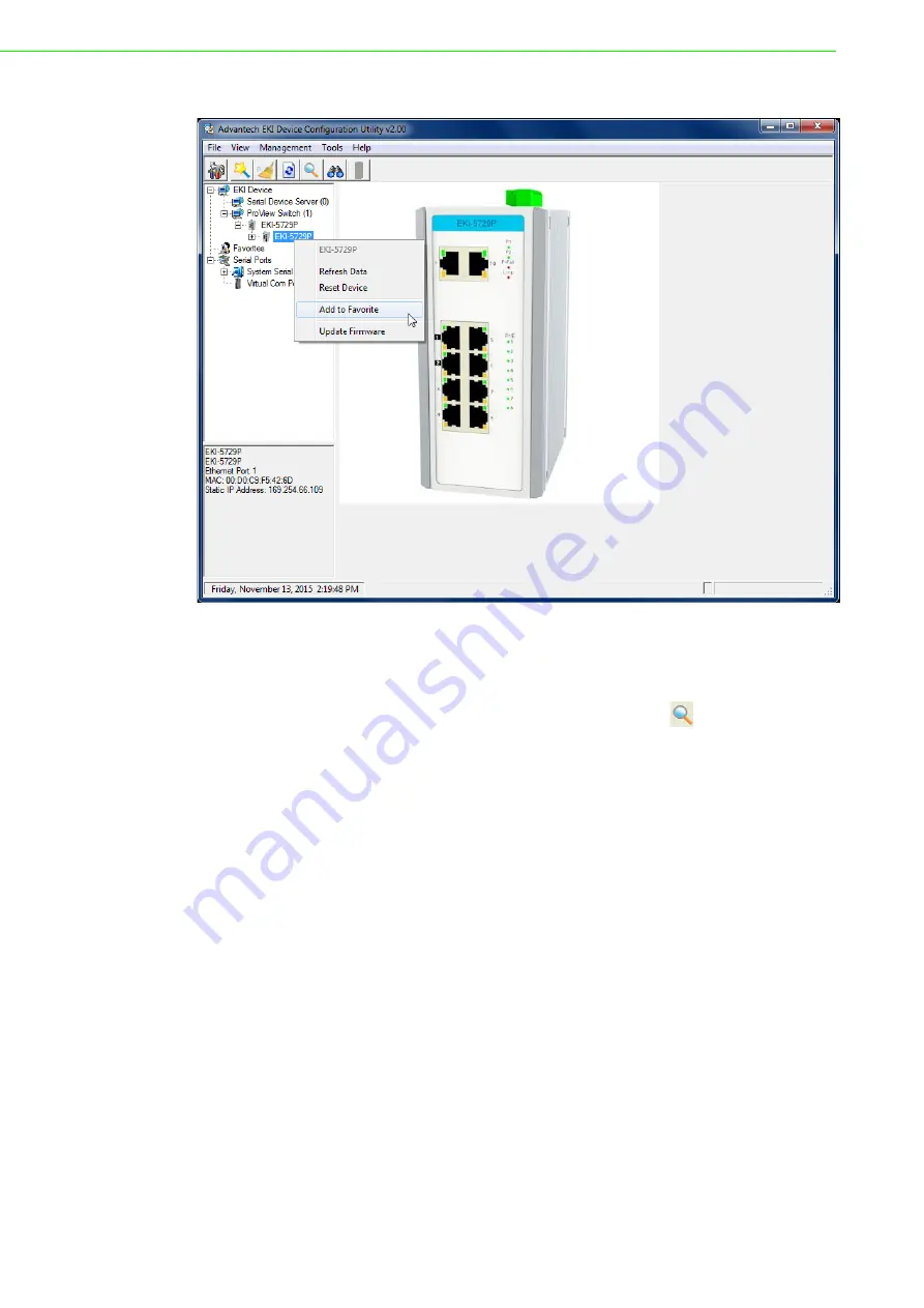
Select 

Add to Favorite

.

Figure 4.6 Adding a Switch to Favorites

In the event that there are existing groups, you can select the specific favorite group
to include the selected device.

Adding an IP Address

1.

From the Tool Bar, click the 

Add IP Address to Favorite


button.

2.

Enter an IP address.

Summary of Contents for EKI-5624PI

Page 1: ...User Manual EKI 5729PI EKI 5624PI ProView Series Ethernet Switches...

Page 2: ...tallation Advantech assumes no liability under the terms of this warranty as a consequence of such events Because of Advantech s high quality control standards and rigorous testing most of our custome...

Page 3: ...uipment is operated in a commercial environment This equipment generates uses and can radiate radio frequency energy and if not installed and used in accordance with the instruction manual may cause h...

Page 4: ...from humidity 6 Put this equipment on a reliable surface during installation Dropping it or letting it fall may cause damage 7 The openings on the enclosure are for air convection Protect the equipme...

Page 5: ...uipment has obvious signs of breakage 21 DO NOT LEAVE THIS EQUIPMENT IN AN ENVIRONMENT WHERE THE STORAGE TEMPERATURE MAY GO BELOW 20 C 4 F OR ABOVE 60 C 140 F THIS COULD DAMAGE THE EQUIPMENT THE EQUIP...

Page 6: ...nte einen Brand bzw elektrischen Schlag aus l sen 13 ffnen Sie niemals das Ger t Das Ger t darf aus Gr nden der elektrischen Sicherheit nur von authorisiertem Servicepersonal ge ffnet werden 14 Wenn f...

Page 7: ...from damage To avoid electrical shock always disconnect the power from your PC chassis before you work on it Don t touch any components on the CPU card or other cards while the PC is on Disconnect pow...

Page 8: ...stallation 14 2 4 Connecting the Switch to Ethernet Ports 15 2 4 1 RJ45 Ethernet Cable Wiring 15 Figure 2 6 Ethernet Plug Connector Pin Position 15 2 5 Power Supply Installation 16 2 5 1 Overview 16 F...

Page 9: ...4 Managing Switch 31 4 1 Discovering Switches 32 4 1 1 First Time Installation 32 Figure 4 1 Selecting Networking Setting 32 Figure 4 2 Configuring a Static IP Setting 33 4 1 2 Discovering Switches 34...

Page 10: ...Chapter 1 1 Product Overview...

Page 11: ...em perature Wide Temperature 40 C 75 C 40 F 167 F Standard Temperature 25 C 60 C 4 F 140 F Storage Tempera ture 40 C 85 C 40 F 185 F Ambient Relative Humidity 10 95 non condensing Switch Properties MA...

Page 12: ...1 Front View EKI 5624PI 4PI 6 5 P1 P2 P Fail Loop PoE 1 2 3 4 3 4 1 2 5 2 3 4 1 No Item Description ETH port Two 10 100 1000BaseT X ports ETH port Four 10 100BaseT X with PoE ports LNK ACT LED Link ac...

Page 13: ...1 P2 P Fail Loop PoE 1 2 3 4 5 6 7 8 EKI 5729PI 5 2 3 4 1 No Item Description ETH port Two 10 100 1000BaseT X ports ETH port Eight 10 100 1000BaseT X with PoE ports LNK ACT LED Link activity LED Speed...

Page 14: ...lled PW2 LED Solid green Powered up Off Powered down or not installed P Fail Solid red When PW1 or PW2 is disconnected the LED lights Off When PW1 and PW2 is connected the LED is off Loop Solid red Wh...

Page 15: ...24PI User Manual 1 2 2 Rear View The following view applies to EKI 5624PI and EKI 5729PI Figure 1 4 Rear View No Item Description DIN Rail mounting plate Mounting plate used for the installation to a...

Page 16: ...ies to EKI 5624PI and EKI 5729PI Figure 1 5 Top View 1 2 4 Bottom View The following view applies to EKI 5624PI and EKI 5729PI Figure 1 6 Bottom View V2 V2 PWR2 PWR1 P Fail V1 V1 DC12 24V 1A 24V 1 No...

Page 17: ...Chapter 2 2 Switch Installation...

Page 18: ...und the switch does not exceed 95 percent noncondens ing Altitude at the installation site is not higher than 10 000 feet In 10 100 and 10 100 1000 fixed port devices the cable length from the switch...

Page 19: ...pply Installation on page 16 At startup POST the System LED blinks green while the remaining LEDs are a solid green Once the switch passes POST self test the System LED turns green The other LEDs turn...

Page 20: ...following guidelines for further infor mation Installing the DIN Rail Mounting Kit 1 Insert the top back of the mounting bracket over the DIN rail 2 Push the bottom of the switch towards the DIN rail...

Page 21: ...will need to remove the DIN rail plate 1 Rotate the device to the rear side and locate the DIN mounting plate 2 Remove the screws securing the DIN mounting plate to the rear panel of the switch 3 Rem...

Page 22: ...the screw holes 8 Drill four holes over the four marked locations on the wall keeping in mind that the holes must accommodate wall sinks in addition to the screws 9 Insert the wall sinks into the wall...

Page 23: ...te over the screws on the wall 12 Install the wall mount plate on the screws and slide it forward to lock in place see the following figure Figure 2 5 Wall Mount Installation 13 Once the device is ins...

Page 24: ...he RJ45 Ethernet ports are metallic and con nected to the GND terminal For best performance use shielded cabling Shielded cabling may be used to provide further protection Figure 2 6 Ethernet Plug Con...

Page 25: ...lowing guidelines before wiring the device The Terminal Block CN1 is suitable for 12 24 AWG 3 31 0 205 mm2 Torque value 7 lb in The cross sectional area of the earthing conductors shall be at least 3...

Page 26: ...conduit may cause signal interference To avoid interference and signal degra dation route power and communications wires through separate con duits Caution Do not disconnect modules or cabling unless...

Page 27: ...r input 2 is used for wiring a redundant power configuration See the following for terminal block connector views Figure 2 10 Terminal Receptor Power Input Contacts for PoE models To wire the power in...

Page 28: ...e negative positive DC wires into the V V terminals of PW1 If setting up power redundancy connect PW2 in the same manner 5 Tighten the wire clamp screws to secure the DC wires in place Figure 2 12 Ins...

Page 29: ...I 5729PI EKI 5624PI User Manual If there is no gap between the terminal block and the terminal receptor the ter minal block is seated correctly Figure 2 13 Securing a Terminal Block to a Receptor 1 A...

Page 30: ...Chapter 3 3 Configuration Utility...

Page 31: ...Before continuing further any devices selected for configuration must be connected and powered on see Installation Guidelines on page 9 1 From your Windows desktop locate the Start button to open the...

Page 32: ...ility CD ROM into the CD ROM drive whereas E is the drive name of your CD ROM on the host PC 2 Use Windows explorer or the Windows Run command to execute the setup pro gram the path for the setup prog...

Page 33: ...Shield Wizard screen displays click Next to proceed with the installation Figure 3 2 InstallShield Wizard 1 of 4 5 The Software License Agreement displays press I Agree to continue or Cancel to stop t...

Page 34: ...llation path is C Program Files EKI Device Configuration Utility Figure 3 4 InstallShield Wizard 3 of 4 6 Once the installation of the package is finished a Configuration Utility Setup screen displays...

Page 35: ...re 3 6 Configuration Utility Overview 4 3 2 6 1 5 No Item Description 1 Menu Bar Displays File View Management Tools and Help 2 Tool Bar Useful management functions shortcuts 3 Tree View All devices w...

Page 36: ...dows on load to the maximum value Log Settings Show Log Message Win dow Check the checkbox to show the log message Save Log to File Check the checkbox to save log to file Browse Click Browse to choose...

Page 37: ...e to auto detection time 1 means disable auto detection Auto detect devices every X second Enter a value to specify the time to auto detect devices Check device alive every X second Enter a value to s...

Page 38: ...group of device to Favorites Manual Direct Mapping Virtual COM Port Click to add a target by selecting a Device Type and inputting the IP address physically connecting the serial device server to the...

Page 39: ...lity Menu Map on page 26 3 8 Information Panel The Information Panel area displays the selected device s related information See Utility Menu Map on page 26 3 9 Status Bar The Status Bar area displays...

Page 40: ...Chapter 4 4 Managing Switch...

Page 41: ...lity provides two ways to configure network settings DHCP Auto IP Settings or Static Settings DHCP Auto IP Settings 1 Select Ethernet under the desired device 2 Click the drop down menu to select DHCP...

Page 42: ...EKI 5729PI EKI 5624PI User Manual 33 4 Click Apply to confirm the settings Figure 4 2 Configuring a Static IP Setting...

Page 43: ...Auto Search Only devices within the same network domain can be listed through the search func tion Once a device is listed the features and configuration details are accessible by clicking on the devi...

Page 44: ...g of the devices You can use the Search function again to detect any devices connected to the network domain 4 1 3 Group Management Creating Groups Groups are best used to identify a set of devices wi...

Page 45: ...vorite s List A favorite s list is simple a way to organize the available devices by a category There are three ways to create a favorite s list selecting a device selecting an IP address and selectin...

Page 46: ...igure 4 6 Adding a Switch to Favorites In the event that there are existing groups you can select the specific favorite group to include the selected device Adding an IP Address 1 From the Tool Bar cl...

Page 47: ...Figure 4 7 Add Favorite In the event that there are existing groups you can select the specific favorite group to include the selected IP address Adding an IP Address Range 1 From the Tool Bar click...

Page 48: ...vent that there are existing groups you can select the specific favorite group to include the selected IP address range 4 1 4 Configuring the System Changing Device Name 1 Select the device to configu...

Page 49: ...System tab 3 Locate the Modbus TCP Host Idle Time s field 4 Enter a variable representing the idle time for the Modbus TCP host function ProView provides the following information to SCADA through Mod...

Page 50: ...ity capabilities and neighbors throughout the network 4 Enter a variable representing the idle time for sending of LLDP information Setting Networks Parameters For setting networks parameters see Conf...

Page 51: ...e Configuration Area select the PoE tab 3 Select the radio box next to the target port then click on it to check and enable the PoE function on that port To disable the PoE function on the port click...

Page 52: ...EKI 5729PI EKI 5624PI User Manual 43 Temperature Celsius Figure 4 12 Setting Modbus TCP Idle Time...

Page 53: ...escription System Info Vendor ID 0x 13FE 1 word 16 bits HEX 0x0000 30001 Vendor ID 0x13FE Unit ID 0xFF 1 word 16 bits HEX 0x0001 30002 Unit ID 0xFF Product Code 1 word 16 bits HEX 0x0002 30003 Product...

Page 54: ...Name YYY xxxxx Word 0 Hi byte Y Word 0 Lo byte Y Word 1 Hi byte Y Word 1 Lo byte Word 2 Hi byte x Word 2 Lo byte x Word 3 Hi byte x Word 3 Lo byte x Word 4 Hi byte x Word 4 Hi byte 0 IP Address 2 word...

Page 55: ...000 10M Half 0x0001 10M Full 0x0002 100M Half 0x0003 100M Full 0x0004 1000M Half 0x0005 1000M Full 0xFFFF No port Port 1 Speed 1 word 16 bits HEX 0x1100 34353 Port 2 Speed 1 word 16 bits HEX 0x1101 34...

Page 56: ...1400 35121 Port 2 Descrip tion 20 words 40 chars ASCII 0x1414 35141 Port 3 Descrip tion 20 words 40 chars ASCII 0x1428 35161 Port 4 Descrip tion 20 words 40 chars ASCII 0x143C 35181 Port 5 Descrip tio...

Page 57: ...Up Coun ter 1 word 16 bits HEX 0x1705 35894 Port 7 Link Up Coun ter 1 word 16 bits HEX 0x1706 35895 Port 8 Link Up Coun ter 1 word 16 bits HEX 0x1707 35896 Port 9 Link Up Coun ter 1 word 16 bits HEX...

Page 58: ...Current 1 word 16 bits HEX 0x1822 36179 Port 4 PoE Current 1 word 16 bits HEX 0x1823 36180 Port 5 PoE Current 1 word 16 bits HEX 0x1824 36181 Port 6 PoE Current 1 word 16 bits HEX 0x1825 36182 Port 7...

Page 59: ...0x0020 Port 1 PoE Tempera ture 1 word 16 bits HEX 0x1860 36241 Port 2 PoE Tempera ture 1 word 16 bits HEX 0x1861 36242 Port Info Port 3 PoE Tempera ture 1 word 16 bits HEX 0x1862 36243 Port 4 PoE Temp...

Page 60: ...x2014 38213 Port 7 Tx Packets 4 words 64 bits HEX 0x2018 38217 Port 8 Tx Packets 4 words 64 bits HEX 0x201C 38221 Port 9 Tx Packets 4 words 64 bits HEX 0x2020 38225 Port 10 Tx Packets 4 words 64 bits...

Page 61: ...Word 1 0x4130 Port 1 Tx Error Packets 2 words 32 bits HEX 0x2200 38705 Port 2 Tx Error Packets 2 words 32 bits HEX 0x2202 38707 Port 3 Tx Error Packets 2 words 32 bits HEX 0x2204 38709 Port 4 Tx Error...

Page 62: ...Rx Error Packets 2 words 32 bits HEX 0x2304 38965 Packet Info Port 4 Rx Error Packets 2 words 32 bits HEX 0x2306 38967 Port 5 Rx Error Packets 2 words 32 bits HEX 0x2308 38969 Port 6 Rx Error Packets...

Page 63: ...54 EKI 5729PI EKI 5624PI User Manual...

Page 64: ...tions are subject to change without notice No part of this publication may be reproduced in any form or by any means electronic photocopying recording or otherwise without prior written permis sion of...

Reviews: