56
- FORM NO. 56043111 - Adhancer
™
ELECTRICAL SYSTEM
SERVICE TEST MODE:
To assist in the troubleshooting and servicing of the electrical system and related components on the Adhancer™ scrubbers, a special test mode that allows
independent control of the various outputs and monitoring of the various inputs has been incorporated.
To enter the service test mode perform the following step:
Turn the main power Key Switch
1
(A)
to the Off position.
Press and hold the Wand Switch
2
(E)
.
While holding the Wand Switch, turn the Key Switch to the On position.
3
Continue to hold the Wand Switch until the Wand Indicator
4
(M)
turns green.
Release the Wand Switch. The Display
5
(D)
will now display “
SVCTEST
” and the current battery voltage and speed control status (SCS).
Note:
The function of each switch and indicator is described below.
To exit this mode, turn the main Key Switch to the Off position.
6
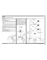
INPUT INDICATORS (
SEE FIGURE 6 FOR PANEL DISPLAY AND BUTTON LOCATIONS
):
SCS:
The speed control status signal is an output from the speed control to the main control unit that indicates the status of the speed control. Normally this indicator will
be displayed whenever the key is on. If there is a speed control fault, this indicator will
fl
ash the fault code produced by the speed control. Refer to the speed control
section for details on these codes.
If
SCS
does not display, follow the troubleshooting procedures below:
Disconnect the ORN/BLU wire from the speed controller and main controller and check the continuity of the wire.
If the wire tests open, repair or replace the wire or plug.
If wire tests OK, replace the speed controller.
F/R:
The speed control forward/reverse signal is an output from the speed control to the main control unit that indicates when the throttle has been moved from the neutral
position to either forward or reverse.
F/R
will be displayed if this signal is active.
If
F/R
does not display, follow the troubleshooting procedures below:
Disconnect the RED/BLK wire from the speed controller and main controller and check the continuity of the wire.
If the wire tests open, repair or replace the wire or plug.
If the wire tests OK, replace the speed controller.
REV:
The speed control reverse signal is an output from the speed control to the main control unit that indicates when the throttle has been moved to the reverse position.
REV
will be displayed if this signal is active.
If
REV
does not display, follow the troubleshooting procedures below:
Disconnect the BLU/BLK wire from the speed controller and main controller and check the continuity of the wire.
If the wire tests open, repair or replace the wire or plug.
If wire tests OK, replace the speed controller.
Summary of Contents for Adhancer 56316001(W32-C)
Page 1: ...7 08 FORM NO 56043111 SERVICE MANUAL Models 56316000 W28 C 56316001 W32 C Adhancer...
Page 2: ......
Page 7: ...FORM NO 56043111 Adhancer 5 TECHNICAL SPECIFICATIONS...
Page 25: ...FORM NO 56043111 Adhancer 23 SCRUB SYSTEM FIGURE 2...
Page 51: ...FORM NO 56043111 Adhancer 49 FIGURE 4...
Page 53: ...FORM NO 56043111 Adhancer 51 FIGURE 5 ELECTRICAL SYSTEM...
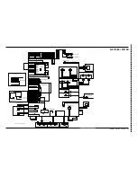
Page 59: ...FORM NO 56043111 Adhancer 57 FIGURE 6 ELECTRICAL SYSTEM...
Page 68: ......
Page 74: ......


