


FORM NO. 56043111 - Adhancer
™
-
43
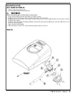
WHEEL DRIVE SYSTEM
(5K) POTENTIOMETER (R1) INSTALLATION AND ADJUSTMENT (CONTINUED)
Reconnect the ohmmeter leads to the terminals
7
1 Low
and
2 Wiper
, then rotate the pot so the ohmmeter reads approximately 2.5k
or half the total pot
resistance. This will accurately set the true neutral drive paddle position.
Tighten the anchor nut.
8
Note
: Do not turn the potentiometer shaft when tightening the anchor nut.
Reattach the connectors to R1 and R2, then reinstall the Front Cover Paddle
9
(G)
.
Reconnect the battery connector, turn the key switch on and test the drive system for proper forward and reverse operation.
10
Note
: Turn pot R2 to the full-
clockwise (fast) position for testing. If the display panel shows the 03 fault code the potentiometers are either wired incorrectly, or the R1 pot is not set to its
neutral setting. Readjust as necessary as outlined above.
(100K) POTENTIOMETER (R2) TESTING AND REMOVAL
WARNING!
Disconnect the battery connector before servicing.
Note
: You do not need to remove potentiometer (pot) R2 from the Front Cover Paddle to test it.
Testing the 100K Speed Limiting Potentiometer R2
See Figure 7.
1
Remove the four Screws
(I)
holding the Front Cover Paddle
(G)
to the Back Cover
Paddle
(H)
. Note that pot
(R2)
is mounted to Front Cover Paddle.
See Figure 7 and Figure 10.
2
Note the color and location of the three wires connected to Pot
R2
, disconnect the wires from
R2
, then remove the Front Cover Paddle
(G)
and attached
R2
from the Back Cover Paddle
(H)
.
Use an ohmmeter to measure the resistance across the two outer high and low terminals (
3
White
and
Black
in Figure 10) to check the total resistance of the potentiometer. If the potentiometer is
working correctly, the resistance across the two outer terminals should measure approximately
100k
.
Use an ohmmeter to measure the resistance across the pot high and middle wiper terminals
4
(
Black
and
Brown
in Figure 10). If the potentiometer is working correctly, the resistance across
the high and wiper terminals should measure close to 0
with the speed limit control knob
turned all the way clockwise (fast speed), and approximately 100k
with the knob rotated all
the way counterclockwise (slow speed).
Use an ohmmeter to measure the resistance across the pot low and middle wiper terminals
5
(
White
and
Brown
in Figure 10). If the potentiometer is working correctly, the resistance across
the low and wiper terminals should measure approximately 100k
with the speed limit control
knob turned all the way clockwise (fast speed), and close to 0
with the knob rotated all the way
counterclockwise (slow speed).
If the resistance values you get are not similar to those measured in steps 3 through 5 above,
6
replace the potentiometer.
Removing and Installing Potentiometer R2
See Figure 10.
1
Remove the Setscrew
(L)
(1/16” wrench) and pull the adjustment Knob
(M)
off
of the pot shaft.
Remove the anchor nut (1/2 inch wrench) then remove the star washer and pot
2
(R2)
from the
Front Cover Paddle
(G)
.
Install the replacement pot into the Front Cover Paddle
3
(G)
, reinstall the star washer, then
reinstall and tighten the anchor nut.
Reinstall the adjustment Knob
4
(M)
onto the pot shaft, then tighten the Setscrew
(L)
.
Check the position of the gray indicator on the Knob
5
(M)
with the pot set to both the full clockwise
(fast) and full counterclockwise (slow) positions. Readjust the rotational position of the Knob on
the pot shaft as necessary to center the indicator to the Front Cover Paddle
(G)
.
Reconnect the three wires to the corresponding terminals on the pot as noted in step 2 in the
6
Testing the 5K Directional/Throttle Potentiometer R1
section.
See Figure 7.
7
Reassemble the Front Cover Paddle
(G)
to the Back Cover Paddle
(H)
.
FIGURE 8
FIGURE 9
FIGURE 10
Summary of Contents for Adhancer 56316001(W32-C)
Page 1: ...7 08 FORM NO 56043111 SERVICE MANUAL Models 56316000 W28 C 56316001 W32 C Adhancer...
Page 2: ......
Page 7: ...FORM NO 56043111 Adhancer 5 TECHNICAL SPECIFICATIONS...
Page 25: ...FORM NO 56043111 Adhancer 23 SCRUB SYSTEM FIGURE 2...
Page 51: ...FORM NO 56043111 Adhancer 49 FIGURE 4...
Page 53: ...FORM NO 56043111 Adhancer 51 FIGURE 5 ELECTRICAL SYSTEM...
Page 59: ...FORM NO 56043111 Adhancer 57 FIGURE 6 ELECTRICAL SYSTEM...
Page 68: ......
Page 74: ......