


60
- FORM NO. 56043111 - Adhancer
™
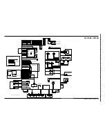
ELECTRICAL SYSTEM
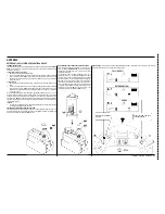
MAIN CONTROL PROGRAMMING OPTIONS
Selection of Low-voltage Cut-out Threshold:
FACTORY DEFAULT: 31.0V (STANDARD)
The Adhancer™ is equipped with a low-voltage cut-out feature to prevent over-discharging the batteries. This feature will automatically shut down the scrub system
when the battery voltage falls to the selected threshold. The cut-out level is adjustable. The Standard setting is 31.0 volts (1.72 volts per cell) and the alternate (Gel
Cell) setting is 33.0 volts (1.83 volts per cell). Select the proper cut-out level based on the battery manufacturer’s speci
fi
cations.
It is important to note that some
maintenance-free batteries (including some gelled electrolyte cells) are capable of being safely discharged down to 1.72 volts per cell.
To select between the two
low-voltage cut-out levels:
Turn the main power Key Switch
1
(A)
to the Off position.
Press and hold the Scrub Off Switch
2
(H)
.
While holding the Scrub Off Switch, turn the Key Switch to the On position.
3
Continue to hold the Scrub Off Switch until the Scrub Off Indicator
4
(J)
turns red.
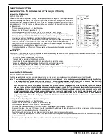
Release the Scrub Off Switch. The LCD will now display “31.0V” or “33.0V”, and the battery icon on the right top corner to indicate that you are in low-voltage
5
cut-out selection mode. The Scrub On Indicators
(K
and
L)
will be alternately green and yellow depending on the cut-out threshold setting.
Press and release the Scrub On Switch
6
(I)
to toggle between the two cut-out voltages. The Scrub On Indicators will alternately toggle between green and yellow
and the display will show the selected cut-off voltage. For the standard cut-out level (factory default), select “31.0V”. For the alternate cut-out level, select
“33.0V”.
Press the Scrub Off Switch to save the new setting. The Scrub Off Indicator will turn green and the display will show the key switch icon prompting you to reset
7
the machine.
Turn the Key Switch to the Off position. The new setting will be saved and will remain in effect until it is changed again.
8
Turning Fault Detection On or Off:
FACTORY DEFAULT: ON
Normally, the main control unit will perform checks of the electrical system during operation. If a fault occurs in a particular system, that system (and possibly others)
will be shut down. This can make troubleshooting the system dif
fi
cult. This option will allow service personnel to disable some of the fault detection checks to
facilitate troubleshooting. This will not disable the over-current protection on any of the systems. To turn the fault checking on or off:
Turn the main power Key Switch
1
(A)
to the Off position.
Press and hold the Scrub Off Switch
2
(H)
and the Solution Switch
(B)
.
While holding both switches, turn the Key Switch to the On position.
3
Continue to hold both switches until the Solution System Indicator
4
(O)
turns yellow.
Release both switches. The LCD will display wrench icons at the two top corners and the Scrub Off Indicator
5
(J)
will turn red.
Press and release the Solution Switch to enable or disable the fault detection mode. The wrench icon in the upper left-hand corner of the display will show a
6
wrench when the fault detection is enabled (switched on), and a wrench with a crossed line through it when the fault detection is disabled (switched off).
Press the Scrub Off switch to save the setting. The Scrub Off Indicator will turn green and the LCD will display the key switch icon prompting you to reset the
7
machine.
Turn the Key Switch to the Off position. The new setting will be saved and will remain in effect until it is changed again.
8
Recall of Stored Error Codes:
Whenever the main control unit detects an electrical system fault, one or more error codes are displayed and stored by the control unit. You can recall and display
these error codes for troubleshooting purposes. To recall stored error codes:
1 Turn the main power Key Switch
(A)
to the Off position.
2 Press and hold the Solution Switch
(B)
.
3 While holding the Solution Switch, turn the Key Switch to the On position.
4 Continue to hold the Solution Switch until the Solution System Indicator
(O)
turns green.
5 Release the Solution Switch. The LCD display will show the wrench icon on the right top corner of the display to indicate that you are in fault recall mode.
• If there are no error codes stored, the display will show the key switch icon prompting you to reset the machine. (No fault). Skip to step 7.
• If there are stored error codes, the display will show the wrench icon and error number next to the wrench, and the Scrub Off Indicator
(J)
will be red. If more
than one error code is stored, it will scroll through the error codes in sequence.
6 • To save the stored error codes, go to step 7.
• To clear the stored error codes, press the Scrub Off Switch
(H)
. The display will show the key switch icon prompting you to reset the machine.
7 To exit the error code recall mode, turn the Key Switch to the Off position.
Summary of Contents for Adhancer 56316001(W32-C)
Page 1: ...7 08 FORM NO 56043111 SERVICE MANUAL Models 56316000 W28 C 56316001 W32 C Adhancer...
Page 2: ......
Page 7: ...FORM NO 56043111 Adhancer 5 TECHNICAL SPECIFICATIONS...
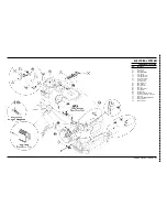
Page 25: ...FORM NO 56043111 Adhancer 23 SCRUB SYSTEM FIGURE 2...
Page 51: ...FORM NO 56043111 Adhancer 49 FIGURE 4...
Page 53: ...FORM NO 56043111 Adhancer 51 FIGURE 5 ELECTRICAL SYSTEM...
Page 59: ...FORM NO 56043111 Adhancer 57 FIGURE 6 ELECTRICAL SYSTEM...
Page 68: ......
Page 74: ......