background image

General Information

29

Service Manual – Advance 7765 / Nilfisk CR1500

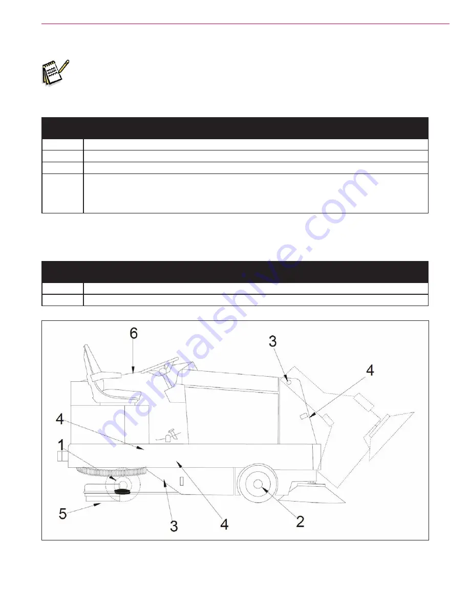
Lubrication Locations

Note:

  Use a good grade multipurpose grease. Avoid using too much grease.

Lubrication Every 100 Hours

Location 

Number

Procedure

1

Lubricate the drive wheel swivel, wheel bearings and steering rack guide

2

Lubricate the front wheel bearings

3

Lubricate all moving joints

4

Lubricate all bushings with Loctite

®

 Silver Grade Anti-Seize compound. Note that the bushings 

are located on the steering, scrub deck lift, squeegee lift, main broom lift, both threaded ends of 

the throttle cable and on the variable dump door cylinders. (Refer to the relevant sections in this 

manual and the Parts List.)

Lubrication Every 250 Hours

Location 

Number

Procedure

5

Lubricate the squeegee casters

6

Clean and lubricate the governor linkage (diesel only)

Summary of Contents for 56514925

Page 1: ...ls 56514925 Variable Dump Gas 56514926 Variable Dump LP 56514927 Variable Dump Diesel 56514928 Manual Dump Gas 56514929 Manual Dump LP GM3 0L 56514930 Manual Dump Diesel S4Q2 56514931 Variable Dump LP Nilfisk CR1500 Models 56514850 Variable Dump Gas 56514852 Variable Dump LP 56514854 Variable Dump Diesel ...

Page 2: ...dump only 18 Jacking the Machine 19 Transporting the Machine 19 Towing or Pushing the Machine 20 Technical Specifications 22 General Specifications 22 Overall Dimensions 23 Engine and Machine Performance 24 Fastener Torque Specifications 24 Maintenance 24 Recommended Service Materials 25 Maintenance Schedules 25 Daily Maintenance 25 Weekly Maintenance Every 50 Hours 26 Maintenance Every 100 Hours ...

Page 3: ...l Description 57 Overview 57 Instrument Panel and Circuit Breakers 57 Foot Pedal Proximity Switches 58 Electrical Ladder Diagrams 59 Electrical Ladder Diagram p n 56382653 Rev B Page 1 59 Electrical Ladder Diagram p n 56382653 Rev B Page 2 60 Electrical Ladder Diagram p n 56382653 Rev B Page 3 61 Electrical Ladder Diagram p n 56382653 Rev B Page 4 62 Electrical Ladder Diagram p n 56382653 Rev B Pa...

Page 4: ... 89 Component Locations 90 LPG and Gasoline 90 LPG 94 Gasoline 96 Firing Order and Plug Wire Routing 97 Maintenance and Adjustments 97 Engine Oil 97 Engine Coolant 98 Checking Engine Coolant 98 Replacing Engine Coolant 98 Engine Air Filter Maintenance 99 Troubleshooting 100 General Troubleshooting 100 Engine Overheating Problems 100 Loss of Oil Pressure Protection 101 Engine Diagnostics 101 To Acc...

Page 5: ...cations 137 Scrub Deck Hydraulic Specifications 138 Transport Circuit Hydraulic Specifications 138 Steering Circuit Hydraulic Specifications 139 Side Broom Hydraulic Specifications GM and Mitsubishi Engines 139 Main Broom Hydraulic Specifications GM Engines 140 Main Broom Hydraulic Specifications Mitsubishi Engines 140 Dust Control System Hydraulic Specifications GM Engines Variable Dump Models 14...

Page 6: ...Running in Reverse 167 Scrub Deck Down at Normal Scrub Pressure 168 Scrub Deck Down at High Scrub Pressure 169 Scrub Deck Up 170 Scrub Deck Up with Engine Shut Off 171 Component Locations 172 Troubleshooting 174 Specifications 176 Component Specifications 176 Special Tools 177 Solution System 178 Functional Description 178 Overview Standard Solution System 178 Solution Tank 179 Solution Flow Contr...

Page 7: ...7 Functional Description 207 Overview 207 Hydraulic Diagrams 209 Power Steering Unit Description 209 Steering Wheel Stationary 209 Steering Wheel Turned Toward the Right 210 Steering Wheel Turned Toward the Left 211 Steering Wheel Held in Full Right or Left Position 212 Turning the Steering Wheel with the Engine Off 213 Maintenance 214 Troubleshooting 215 Removal and Installation 215 Specification...

Page 8: ... Pump 238 Drive Pump Before Machine Serial Number 1000034942 238 Drive Pump After Machine Serial Number 1000034942 239 Forward Reverse Controls 239 Forward Reverse Controls GM Engines Before s n 1000034942 240 Forward Reverse Controls GM Engines After s n 1000034942 240 Foot Pedal Assembly GM Engines 241 Forward Reverse Controls Mitsubishi Diesel Engines Before s n 1000034942 242 Forward Reverse C...

Page 9: ...System The engine drives two hydraulic pumps that power the machine systems All of the motors on the machine are hydraulic except for the electric filter shaker motor The 1 24 cubic inches per revolution CIR drive pump is a variable displacement pump that powers the rear wheel drive motor for propulsion The dual displacement auxiliary gear pump includes two separate 1 02 CIR pumping elements in on...

Page 10: ...System uses three disc scrub brushes and has two selectable scrub pressures The normal scrub setting provides approximately 252 lbs 114 kg of scrub brush pressure The heavy scrub setting provides approximately 600 lbs 272 kg of scrub brush pressure The scrub brushes are powered by individual hydraulic motors A hydraulic cylinder extends and retracts the scrub deck and controls the scrub pressure S...

Page 11: ...variable dump models only The Dust Control System uses an impeller fan driven by a hydraulic motor to pull air from the hopper and through a baffle system and filter to minimize the dust generated from sweeping A pre clean flap restricts the heavier dust particles to an area below the filter The lighter dust particles are trapped in the filter An electric shaker motor controlled by a switch on the...

Page 12: ...0 VD Gas 56514852 VD LP 56514854 VD Diesel 56041714 DA NO SV FI 56041715 DE FR NL RU 56041716 ES PT IT GR 56041717 ET LV LT SL 56041718 SK CS PL HU 56041719 US TR 56042488 These manuals can be found on the following Nilfisk Advance s electronic supported databases Nilfisk Advance Dealer Customer Zone Advance website www advance us com Nilfisk website www nilfisk com EzParts service parts CD ROM En...

Page 13: ...ment Digital voltmeter DVM with DC current clamp Hydrometer Battery load tester for checking 12V batteries Automotive fuel pressure test gauge used on gasoline engines Set of torque wrenches These tools are also available from Nilfisk Advance Inc PSI engine service kit p n 56109084 includes an LPG Test Kit p n 56504450 and a Diagnostic Communication Cable and software p n 56305647 PSI engine servi...

Page 14: ...eneration 1 old style p n 56109083 Hydraulic test gauge w connector 3000 psi range p n 56504516 Vacuum water lift gauge p n 56205281 PSI diagnostics cable 4 pin 8 pin Generation 1 old style p n 56109083 Hydraulic test gauge w connector 3000 psi range p n 56504516 Vacuum 70 60 50 40 30 20 10 0 80 90 100 ...

Page 15: ...ventory of Nilfisk Advance original replacement parts and accessories Call the Nilfisk Advance Dealer named below for repair parts or service Please specify the Model Number same as the Part Number and Serial Number when discussing your machine Dealer affix service sticker here Nameplate The Model Number and Serial Number of the machine are shown on the Nameplate located on the front of the hydrau...

Page 16: ... that could cause severe personal injury This machine should only be used by properly trained and authorized personnel While on ramps or inclines avoid sudden stops when loaded Avoid abrupt sharp turns Use low speed down hills Clean only while ascending driving up the ramp Keep sparks flame and smoking materials away from the battery Explosive gases are vented during normal operation Charging the ...

Page 17: ... instructions pertaining to that function Do not leave the machine unattended without first turning the Key Switch off O removing the key and securing the machine Apply the parking brake before exiting the Operator s seat Turn the Key Switch off O and remove the key before changing the brushes and before opening any access panels Take precautions to prevent hair jewelry or loose clothing from beco...

Page 18: ...ock Arm before working under the hopper The Safety Lock Arm is mounted to the right side of the frame and swings up to align with and support the bottom of the hopper as shown Warning Never work under the hopper without first engaging the Safety Lock Arm After the work under the hopper is complete swing the Safety Lock Arm back down to its disengaged position Safety Lock Arm shown in engaged posit...

Page 19: ...s as shown below Transporting the Machine Caution Before transporting the machine on an open truck or trailer make sure the machine is tied down securely at the designated Tie Down Jacking Locations shown below all access doors and covers are secured tape and strap as needed and the parking brake is engaged The jacking and tie down locations are identified with a decal on the body panel Front Jack...

Page 20: ...with a tow bypass valve that opens the hydraulic circuit to the wheel drive motor This allows the wheel drive motor to freewheel when the machine is being towed pushed short distances without the use of the engine The tow valve is controlled by the Tow Valve Extension Shaft located on top of the drive pump just in front of the engine Tow Valve Extension Shaft ...

Page 21: ... the machine in forward or reverse Attempting to operate the machine with the tow valve in the bypass towing position can cause overheating of the hydraulic system and or reduced operating performance Tow or push the machine no faster than a normal walking pace 2 3 miles per hour 3 5 kilometers per hour and for no farther than 300 feet 100 meters Towing or pushing the machine farther than 300 feet...

Page 22: ...sly variable Off solution level pulled back to off position Approximately 1 GPM 6 6 LPM at low setting Approximately 3 GPM 13 2 LPM at high setting Sweeping Path Variable Dump Models 60 in 152 cm Manual Dump Models 50 in 127 cm Main Broom 50 in 127 cm long 14 in 35 5 cm dia Side Broom optional on Manual Dump Models 24 in 61 cm Dust Filter Variable Dump Models 107 ft2 10 m2 Manual Dump Models N A H...

Page 23: ...General Information 23 Service Manual Advance 7765 Nilfisk CR1500 Overall Dimensions Machine Length Machine Height Machine Width ...

Page 24: ... lb 28 in lb 1 4 100 in lb 67 in lb 5 16 17 ft lb 11 ft lb 3 8 31 ft lb 20 ft lb 1 2 75 ft lb 50 ft lb 3 4 270 ft lb 180 ft lb M5 61 in lb 36 in lb M6 9 ft lb 62 in lb M8 22 ft lb 13 ft lb M10 44 ft lb 25 ft lb M12 70 ft lb 40 ft lb Maintenance Keep the machine in top condition by closely following the maintenance schedule Maintenance intervals given are for average operating conditions Machines u...

Page 25: ... leaks radiator core blockage 11 Check the air cleaner 9 Check for LP diesel odor at connections 10 Check the water separator diesel if so equipped Hydraulic system 3 Check the oil level in the hydraulic oil reservoir Check for any hydraulic leaks 12 Check the hydraulic oil filter Recovery tank 16 Drain and clean the inside of the tank flush with clean water 16 Check the cover perimeter gasket for...

Page 26: ...e squeegees 19 Check for wear and damage Hydraulic hoses 22 Check for wear cuts or leakage Hopper 24 Clean or replace the hopper panel filter Variable Dump only Maintenance Every 100 Hours Maintenance Item Location Number Procedure Engine Perform recommended engine maintenance see applicable engine manual Drive wheel and steering components 27 Make sure to grease the fittings on the rear wheel sup...

Page 27: ...if applicable Inspect and drain any oil buildup from the LP fuel system electronic pressure regulator EPR LPG only Hydraulic system 40 Replace the hydraulic filter element Squeegee casters 32 Lubricate Solution tank 14 Clean the solution tank 33 Clean the pump inlet strainer Maintenance Every 400 Hours Maintenance Item Location Number Procedure Engine Perform any additional recommended engine main...

Page 28: ...General Information 28 Service Manual Advance 7765 Nilfisk CR1500 Maintenance Item Locations ...

Page 29: ...ront wheel bearings 3 Lubricate all moving joints 4 Lubricate all bushings with Loctite Silver Grade Anti Seize compound Note that the bushings are located on the steering scrub deck lift squeegee lift main broom lift both threaded ends of the throttle cable and on the variable dump door cylinders Refer to the relevant sections in this manual and the Parts List Lubrication Every 250 Hours Location...

Page 30: ...ntrol on off and flow volume A L 13 Detergent solution pump ESP Recycle option only L 14 Squeegee system raise lower and auto lift in reverse 15 Vacuum system performance sealed water lift 30 76 cm rated engine speed C L 16 Headlights gauges and optional accessories 17 Seat adjustment lever Ref VISUAL INSPECTION ITEMS Comments OK Defect Codes circle Does Not Work 18 Main broom motor B L 19 Main br...

Page 31: ...rd reverse controls A B D 48 Gasoline Diesel fuel tank filter and lines Xx hours C L W 49 LP tank hoses and fittings L W 50 LP fuel filter service life 400 Hrs C 51 LPG vaporizer Remove oil buildup every 150 hours or 120 days C 52 LP fuel regulator lock off valve and hoses L 53 Diesel glow plug function light hard starting 54 Gasoline and Diesel fuel tank strainer yearly C 55 Brake cable and parki...

Page 32: ...w Major Machine Components Main Broom Scrub Deck Scrub Brush 3 Hopper Side Broom Filter Panel Pump Inlet Strainer Solution Tank Recovery Tank Solution Line from Solution Tank to Scrub Brushes Vacuum Hose from Squeegee to Recovery Tank Engine Cover Rear Squeegee Assembly Scrub Brush Motor 3 ...

Page 33: ...nals and instrument panel gauges will operate When the key is turned to the center off position the engine will shut off but the horn and light options will still operate Glow Plug Switch location only shown diesel only Throttle Switch Gasoline LPG toggles the engine between idle turtle icon and operating speed rabbit icon Throttle Lever Diesel location only shown sets the engine speed from idle t...

Page 34: ...Control and Indicator Solution Control Lever controls the solution flow via a mechanical linkage connected to a ball valve in the solution supply line The solution flow rate is continuously variable from No Flow Solution Control Lever by the narrow white line to a maximum of 3 GPM Solution Control Lever by the wide white line Note Unless the machine is equipped with the Solution Off in Neutral Opt...

Page 35: ... speed detergent output Scrub System Controls Scrub Brush Lift Switch controls the scrub deck and scrub brush motors as follows Pressing the switch to the lower position will lower the scrub deck and switch on the three scrub brush motors Pressing the switch to the raise position will raise the scrub deck and switch off the three scrub brush motors Brush Pressure Switch controls the scrub deck pre...

Page 36: ...lade Switch controls the squeegee and recovery vacuum motor as follows Pressing the switch to the lower position will lower the squeegee and switch on the recovery system vacuum motor Pressing the switch to the raise position will raise the squeegee and switch off the recovery system vacuum fan motor Note A proximity switch adjacent to the drive foot pedal will automatically raise the squeegee and...

Page 37: ...ge to the following three positions Moving the Main Broom Lift Control to the Float Position will allow the main broom to float on the floor under its own weight This setting produces a 4 5 10 13 cm broom pattern and is used for heavy sweeping or irregular surfaces Moving the Main Broom Lift Control to the Sweep Position lowers the main broom to the normal sweep position and produces a 2 3 5 8 cm ...

Page 38: ...ing the switch to the off lower position will switch off the side broom Side Broom Lift raises and lowers the side broom via a cable actuated by the Side Broom Lift Knob To raise the side broom press the Lock Button pull the Side Broom Lift Knob then release the Lock Button To lower the side broom press the Lock Button push the Side Broom Lift Knob forward then release the Lock Button Side Broom S...

Page 39: ...er Dump Door Lever mechanically actuates the hydraulic valves for the dump door cylinder to open and close the hopper dump door as follows Moving the Hopper Dump Door Lever to the Dump Door Open position will open the hopper dump door Moving the Hopper Dump Door Lever to the Dump Door Close position will close the hopper dump door Note The main broom side broom dust control motor and filter shaker...

Page 40: ...haker motor on and off as follows Pressing the switch to the on upper position will switch on the shaker motor Pressing the switch to the off lower position will switch off the shaker motor Miscellaneous Controls Horn Push Button sounds the horn when pressed Light Switch location only shown switches on the head lights tail lights and instrument lights if the machine is so equipped Turn Signal opti...

Page 41: ... when depressed Accelerator and Directional Control Pedal controls the machine direction and speed Parking Brake Lever raising the Parking Brake Lever to the upright position will lock the Foot Brake Pedal in the down position Foot Brake Pedal Accelerator and Direction Control Pedal Parking Brake Lever shown in engaged position ...

Page 42: ...el Filter The curved black arrows show the airflow The Panel Filter traps the fine dust particles to minimize the dust in the air around the machine An electric Shaker Motor controlled by the filter shaker switch on the instrument panel vibrates the Panel Filter to dislodge dust clogging the Panel Filter to minimize maintenance and extend Panel Filter life Note that the Hopper and hopper door must...

Page 43: ...llow the generated vibration to be transferred to the Panel Filter The two Knob Assemblies fasten the Filter Clamp Weldment and attached components to the horizontal support plate on the front of the hopper Dust Control Vacuum Fan Motor Assembly The hydraulic Dust Control Vacuum Fan Motor drives the Impeller which creates the airflow through the hopper and Panel Filter The Dust Control Vacuum Fan ...

Page 44: ...o operate the main broom with the dust control motor off When the Dust Control Solenoid 1 valve is de energized open it allows the hydraulic oil to flow from the discharge side of the main broom motor through the Dust Control Solenoid 1 valve and to Port 2 on the Main Control Valve bypassing the dust control motor When the Dust Control Solenoid 1 is energized it closes to direct the oil flow from ...

Page 45: ...ition will energize the Dust Control Solenoid 1 to its closed position This directs the oil to the dust control motor Note that the Hopper Switch and the Hopper Door Switch must both be closed for the dust control vacuum fan motor main broom motor and Shaker Motor to operate Shaker Motor Nominal Conditions Filter Shaker Switch On Filter Shaker Switch Off Wire Voltage Voltage 2 B Voltage B Voltage ...

Page 46: ... Dust Control Switch Main Broom and Dust Control Motors Off When the Main Broom Motor and Dust Control Motor are off the Main Broom Solenoid 2 is de energized open This allows the hydraulic oil to flow from the Auxiliary Pump through the non priority leg of the priority flow divider through the open Main Broom Solenoid 2 valve and to the Normal Rotation Brush 4 solenoid valve This bypasses both th...

Page 47: ...be energized to direct the oil from the Main Broom Motor to the Dust Control Motor Machine With Wet Sweep Bypass Option 0 34 CIR 4 50 CIR 75 GPM Dust Control Motor Main Broom Motor 1 2 1 02 CIR 1 24 CIR Return Block Reservoir Auxiliary Pump Drive Pump 9 7 GPM Main Broom Solenoid 2 To Normal Rotation Brush 4 To Side Broom Valve Check Valve Case Drain Case Drain Dust Control Solenoid 1 optional Wet ...

Page 48: ...Main Broom switch is on will run the Main Broom Motor but will switch off the Dust Control Motor In this case the Main Broom Solenoid 2 is energized blocked This allows the hydraulic oil to flow from the Auxiliary Pump through the priority flow divider then to the Main Broom Motor The Dust Control Solenoid 1 will be de energized open to allow the oil from the discharge side of the Main Broom Motor...

Page 49: ... Assembly Main Broom Solenoid Dust Control Solenoid The Panel Filter Filter Clamp Weldment and Filter Shaker Motor Cover are located behind the Filter Access Door on the front of the machine The Filter Shaker Motor Cover shaker motor plate and shaker arms are attached to the shaker motor plate which is held to the Filter Clamp Weldment by the shaker pivot pin Filter Access Door Panel Filter Filter...

Page 50: ...access the Dust Control Vacuum Fan Motor tilt the recovery tank out away from the machine The Case Drain Hose is connected to the hydraulic reservoir The top hydraulic hose is connected to port 2 on the main control valve The bottom hydraulic hose is connected to a union which is connected to the discharge port on the main broom motor Connected to Port 2 on the Main Control Valve Connected to Unio...

Page 51: ...b deck When the Main Broom Solenoid 2 is energized it closes to direct the oil flow through Port 1 on the Main Control Valve The oil is directed through the main broom motor and dust control motor then returns to Port 2 on the Main Control Valve Main Control Valve bottom view shown mounted in assembled machine Main Control Valve Port 1 Port 2 Main Broom Solenoid 2 Main Control Valve top view shown...

Page 52: ...ntrol Filter Maintenance Warning Wear a protective mask to prevent inhaling dust while servicing the filter Wear eye protection while servicing the filter 1 Lift and rotate the Latches then tilt down the Filter Access Door Main Control Valve From Main Broom Motor To Pressure Side of Dust Control Motor To Port 2 on Main Control Valve Dust Control Solenoid 1 To Discharge Side of Dust Control Motor L...

Page 53: ...ter is lightly coated 1 16 inch thick with dirt and the pleats in the filter are not filled with dirt cleaning is not necessary If there is a heavy coating of dirt on the filter clean the filter by following one of the three methods listed below Caution Be careful not to puncture the filter while cleaning Method A a Vacuum any loose dust from the filter b Gently tap the filter against a flat surfa...

Page 54: ...ilter 7 Reinstall the Panel Filter into the machine Make sure the AIRFLOW arrow is pointing up 8 Reinstall the filter clamp weldment and attached shaker motor assembly shaker motor plate and shaker arms into the machine Note that the two vertical tabs on the filter clamp weldment must fit into the matching slots in the rear clamps mounted on the rear of the filter enclosure 9 Reinstall and tighten...

Page 55: ...Solenoid valve not operating correctly Check the solenoid coil resistance If not 7 2 ohms 10 replace the coil Also see the Dust Control System Wiring Diagram The Shaker Motor will not run Circuit breaker CB6 is tripped Reset the circuit breaker No voltage to the Shaker Motor Relay R1 Check for continuity through the hopper and hopper door whisker switches when the hopper is down and the hopper doo...

Page 56: ...pecifications Dust Control Vacuum Fan Motor Displacement 0 00149 gal rev 0 3442 CIR Main Broom Solenoid 2 Valve Dust Control Solenoid 1 Valve Voltage 12 volts Nominal Coil Resistance 7 2 Ohms Initial current draw 1 67 amps Shaker Motor Voltage 12 volts Shaker Relay R1 Coil Resistance 85 5 Ohms ...

Page 57: ...ouses the gauges lights switches and relays that monitor and control the various machine systems The 10 15 amp Circuit Breakers are mounted to the right of the instrument panel 15 amp Circuit Breaker 10 Hour Relay Shaker Relay Forward Relay Reverse Relay R1 R2 R3 R4 Low LP Indicator LPG only Main Broom Switch Voltmeter Oil Pressure Gauge Fuel Gauge Gas Diesel only Side Broom Switch Shaker Motor Sw...

Page 58: ...ved to the reverse drive position it actuates the front Foot Pedal Proximity Switch which actuates the Reverse Relay R3 Note The Foot Pedal Proximity Switch that actuates the forward relay is referred to as the Drive Pedal Forward Sensor on the electrical ladder diagram The Foot Pedal Proximity Switch that actuates the reverse relay is referred to as the Drive Pedal Reverse Sensor on the electrica...

Page 59: ...Y AFTER PLATING AND HEAT TREATING BUT BEFORE PAINTING 4 REMOVE ALL BURRS AND SHARP EDGES APPROVED APPROVED APPROVED CHECKED FIRST USED ON ASSY SIZE CODE TITLE C SCALE PL DRAWN PROJ ENG ORCAD 7 B TO L SW 2 TO L SW 1 TO OPTIONS 24 12 5638263 1 OF 6 DIAGRAM SEE SHEET 2 A 07498 11 10 11 11 10 11 PMO WGL 7765 GAS LPG DIESEL B B B B B B B B B B B B UPDATE AD TO PARTS LIGHT WAS LIGHT A 07901 12 2 2 8 2 9...

Page 60: ...SCALE DRAWING 3 ALL DIMENSIONS APPLY AFTER PLATING AND HEAT TREATING BUT BEFORE PAINTING 4 REMOVE ALL BURRS AND SHARP EDGES APPROVED APPROVED APPROVED CHECKED FIRST USED ON SHEET ASSY SIZE CODE DWG NO TITLE C SCALE PLYMOUTH MINNESOTA 55447 3 DRAWN PROJ ENG NILFISK ADVANCE IN ORCAD ENGINE SYSTEM S4Q2 DIESEL 0895 136 IGNITION START CRANK POWER WATER TEMP SENDER OIL PRESSURE SENDER GLOW PLUG INPUT HO...

Page 61: ...ING 4 REMOVE ALL BURRS AND SHARP EDGES APPROVED APPROVED APPROVED CHECKED FIRST USED ON SHEET ASSY SIZE CODE R DWG NO TITLE C SCALE PLYMOUTH MINNESOTA 55447 340 DRAWN PROJ ENG NILFISK ADVANCE INC ORCAD 56382653 56382653 DIAGRAM LADDER 7765 7760 GAS LPG DIESEL 3 OF 6 3 OF 6 7 7 B B 12 OPTION GAS ONLY 24 REMOVE WIRE WHEN DUST CONTROL SWITCH INSTALLED 11 10 11 11 10 11 PMO WGL REVERSE SENSOR FORWARD ...

Page 62: ...VED CHECKED FIRST USED ON SHEET ASSY SIZE CODE REV DWG NO TITLE C SCALE PLYMOUTH MINNESOTA 55447 3408 DRAWN PROJ ENG B NILFISK ADVANCE INC ORCAD 56382653 56382653 DIAGRAM LADDER 7765 7760 GAS LPG DIESEL 4 OF 6 4 OF 6 7 7 B B RAISE LOWER RAISE TRAVERSE LOWER SEE PAGE 5 FOR MODIFIED CIRCUIT FOR BIOTEC 11 10 11 11 10 11 PMO WGL LOW SOLUTION WARNING LIGHT HIGH RECOVERY WARNING LIGHT B B B B B B B B B ...

Page 63: ...NG 3 ALL DIMENSIONS APPLY AFTER PLATING AND HEAT TREATING BUT BEFORE PAINTING 4 REMOVE ALL BURRS AND SHARP EDGES APPROVED APPROVED APPROVED CHECKED FIRST USED ON ASSY SIZE CODE TITLE C SCALE PLYMOUT DRAWN PROJ ENG ORCAD 56 56382653 DIAGRAM LADD 7760 GAS LPG DIESEL 5 OF 6 7 7 B B RAISE LOWER MODIFIED CIRCUIT FOR BIOTEC 11 10 11 11 10 11 PMO WGL B B B B B B B B B 7 7 18 42 43 18 18 46 46 18 14 40 58...

Page 64: ...ALE DRAWING 3 ALL DIMENSIONS APPLY AFTER PLATING AND HEAT TREATING BUT BEFORE PAINTING 4 REMOVE ALL BURRS AND SHARP EDGES APPROVED APPROVED APPROVED CHECKED FIRST USED ON SHEET ASSY SIZE CODE REV DWG NO TITLE C SCALE PLYMOUTH MINNESOTA 55447 3408 DRAWN PROJ ENG B NILFISK ADVANCE INC ORCAD 56382653 56382653 DIAGRAM LADDER 7765 7760 GAS LPG DIESEL 6 OF 6 6 OF 6 B B ESP RECYCLING OPTION 11 10 11 11 1...

Page 65: ...D APPROVED APPROVED CHECKED FIRST USED ON ASSY SIZE CODE TITLE C SCALE DRAWN PROJ ENG ORCAD 7 B TO L SW 2 TO L SW 1 TO OPTIONS 24 12 56382653 1 OF 6 DIAGRA SEE SHEET 2 A 07498 11 10 11 11 10 11 PMO WGL 7765 GAS LPG DIESEL B UPDATE TO PART LIGHT WA LIGHT A 0790 C A 12724 SHEET 3 12 2 2 8 2 9 28 27 7 11 50 11 11 51 12 11 10 10 17 11 12 32 11 29 33 24 2 1 46 26 101 11 R1 SHAKER RELAY 30 87 N K CHECK ...

Page 66: ...LE DRAWING 3 ALL DIMENSIONS APPLY AFTER PLATING AND HEAT TREATING BUT BEFORE PAINTING 4 REMOVE ALL BURRS AND SHARP EDGES APPROVED APPROVED APPROVED CHECKED FIRST USED ON SHEET ASSY SIZE CODE REV DWG NO TITLE C SCALE PLYMOUTH MINNESOTA 55447 3408 DRAWN PROJ ENG C NILFISK ADVANCE INC ORCAD ENGINE SYSTEM S4Q2 DIESEL 0895 136 IGNITION START CRANK POWER WATER TEMP SENDER OIL PRESSURE SENDER GLOW PLUG I...

Page 67: ...EMOVE ALL BURRS AND SHARP EDGES APPROVED APPROVED APPROVED CHECKED FIRST USED ON ASSY SIZE CODE TITLE C SCALE PLYMOUTH DRAWN PROJ ENG ORCAD 5638 56382653 DIAGRAM LADDE 7760 GAS LPG DIESEL 3 OF 6 7 7 B B 12 OPTION GAS ONLY 24 REMOVE WIRE WHEN DUST CONTROL SWITCH INSTALLED 11 10 11 11 10 11 PMO WGL REVERSE SENSOR FORWARD SENSOR HELD CLOSED BY HOPPER HELD CLOSED BY HOPPER 46 C 86 85 55 63 7 12 12 46 ...

Page 68: ...ED APPROVED APPROVED CHECKED FIRST USED ON SHEET ASSY SIZE CODE R DWG NO TITLE C SCALE PLYMOUTH MINNESOTA 55447 340 DRAWN PROJ ENG NILFISK ADVANCE INC ORCAD 56382653 56382653 DIAGRAM LADDER 7765 7760 GAS LPG DIESEL 4 OF 6 4 OF 6 7 7 B B RAISE LOWER RAISE TRAVERSE LOWER SEE PAGE 5 FOR MODIFIED CIRCUIT FOR BIOTEC 11 10 11 11 10 11 PMO WGL LOW SOLUTION WARNING LIGHT HIGH RECOVERY WARNING LIGHT 7 7 7 ...

Page 69: ... ALL DIMENSIONS APPLY AFTER PLATING AND HEAT TREATING BUT BEFORE PAINTING 4 REMOVE ALL BURRS AND SHARP EDGES APPROVED APPROVED APPROVED CHECKED FIRST USED ON ASSY SIZE CODE TITLE C SCALE DRAWN PROJ ENG ORCAD 56382653 DIAGRA 7760 GAS LPG DIESEL 5 OF 6 7 7 B B RAISE LOWER MODIFIED CIRCUIT FOR BIOTEC 11 10 11 11 10 11 PMO WGL 7 7 18 42 43 18 18 46 46 18 14 40 58 R4 1 SCRUB BRUSH RELAY 85 86 R4 1 SCRU...

Page 70: ...O NOT SCALE DRAWING 3 ALL DIMENSIONS APPLY AFTER PLATING AND HEAT TREATING BUT BEFORE PAINTING 4 REMOVE ALL BURRS AND SHARP EDGES APPROVED APPROVED APPROVED CHECKED FIRST USED ON SHEET ASSY SIZE CODE REV DWG NO TITLE C SCALE PLYMOUTH MINNESOTA 55447 3408 DRAWN PROJ ENG C NILFISK ADVANCE INC ORCAD 56382653 56382653 DIAGRAM LADDER 7765 7760 GAS LPG DIESEL 6 OF 6 6 OF 6 B B ESP RECYCLING OPTION 11 10...

Page 71: ...Engine Harness GM 3 0L Gas p n 56380222 Electrical System 71 Service Manual Advance 7765 Nilfisk CR1500 ...

Page 72: ...Engine Harness GM 3 0L LPG p n 56380221 Electrical System 72 Service Manual Advance 7765 Nilfisk CR1500 ...

Page 73: ...atherpack Connector Two way Male Weatherpack Connector Two way Female Battery Machine Harness Hopper Wire Assembly Hopper Harness Diode Assembly D2 Note These 3 Wires Must Exit Main Harness in the Middle of the Opening for Light Options for the Rest of the Harness to Fit Negative Battery Cable Positive Battery Cable ...

Page 74: ...Engine System common Electrical System 74 Service Manual Advance 7765 Nilfisk CR1500 ...

Page 75: ...Engine Frame Side System Mitsubishi Diesel Electrical System 75 Service Manual Advance 7765 Nilfisk CR1500 ...

Page 76: ...Engine Frame Side System GM Gas Electrical System 76 Service Manual Advance 7765 Nilfisk CR1500 ...

Page 77: ...Engine Frame Side System GM LPG Electrical System 77 Service Manual Advance 7765 Nilfisk CR1500 ...

Page 78: ...Scrub System Electrical Components Part Number Scrub System Electrical System Electrical System 78 Service Manual Advance 7765 Nilfisk CR1500 ...

Page 79: ...Electrical Components Part Number Shaker Motor and Hopper Electrical System Electrical System 79 Service Manual Advance 7765 Nilfisk CR1500 ...

Page 80: ...Electrical Components Part Number Squeegee and Vacuum Fan Motor Electrical System Electrical System 80 Service Manual Advance 7765 Nilfisk CR1500 ...

Page 81: ... TERM 12124580 SOC J SEAL 12015284 16g 12015359 14g 2 13ol 15ol 16ol 18 5ol 1 2 5 38 16 4 5 FIFT 15 14 4 5 FIFT 15 14 4 5 FIFT 39 16 4 5 FIFT 15 14 4 5 FIFT 35 16 4 5 FIFT 15 14 4 5 FIFT 37 16 4 5 FIFT 1 10 4 10R 6 14 5 10R 7 14 5 10R 4 14 6 10R 5 14 6 10R 2 9 14 3 10R 28 14 3 10R 1 14 4 FIFT 24 14 4 FIFT 11 16 6 FIFT 26 16 6 FIFT 15Bol 56 16 2 M BULLET 25 16 2 M BULLET 4 16 25Bol 17 5Bol 18 75Bol...

Page 82: ...are mounted onto a Bracket which is fastened to the back of the Instrument Panel Weldment Early models did not use the R6 power relay which was added around April 2017 Shaker Relay R1 Hour Relay R2 Reverse Relay R3 Forward Relay R4 Power Relay R6 Instrument Panel Weldment Late Model with R6 Power Relay Early Model without R6 Power Relay Instrument Panel Weldment Shaker Relay R1 Hour Relay R2 Rever...

Page 83: ...To access the Circuit Breakers open the solution tank cover Shaker Motor Switch Main Broom Switch Low LP Indicator LPG only High Recovery Warning Light Low Solution Warning Light Brush Pressure Switch Voltmeter Squeegee Blade Switch Water Temperature Gauge Scrub Brush Lift Switch Brush Rotation Switch Hour Meter Oil Pressure Gauge Horn Push Button Ignition Key Switch Dust Control Switch location o...

Page 84: ... the battery voltage and charge as necessary Poor battery connection s Check the battery cables terminals and connections and tighten repair replace as necessary Battery needs to be replaced Perform a load test on the battery and replace if necessary Note Refer to the individual machine system sections for electrical troubleshooting procedures Specifications Component Specifications SPDT Relay R4 ...

Page 85: ...ction pump controls the fuel quantity to maintain the selected RPM or shut the engine off Diesel Engine Wiring Diagram Battery 12 VDC 2 7 7 Bat St Ign Acc Hour Meter 24 12 B Ignition Switch R2 R2 Hour Relay Hour Relay N A 30 87 11 29 46 86 85 50 B B 11 11 101 10 Water Temperature Gauge Oil Pressure Gauge To L Sw 2 N H N K 33 N F N G I S 32 12 I S CB3 15 A 10 2 1 CB4 15 A 11 2 1 CB5 15 A 12 2 1 24 ...

Page 86: ...ositive voltage to the Glow Plug Input terminal J on the 14 pin Engine Harness Connector The St start terminal on the Ignition Switch must provide positive voltage to the Start Crank Power terminal K on the 14 pin Engine Harness Connector For the engine to run the coolant temperature and oil pressure must be within acceptable parameters Component Locations Fuel Injection Nozzle 4 Oil Drain Plug St...

Page 87: ...Engine System Diesel 87 Service Manual Advance 7765 Nilfisk CR1500 Right Side Exhaust Spacer Thermoswitch Fan Alternator Crankshaft Pulley Oil Filter Flywheel Oil Pressure Switch Engine Serial Number ...

Page 88: ...Engine System Diesel 88 Service Manual Advance 7765 Nilfisk CR1500 Murphy Relay Glow Plug Relay Fuel Pump Fuel Filter Starter Solenoid ...

Page 89: ...Engine System Diesel 89 Service Manual Advance 7765 Nilfisk CR1500 Starter Relay ...

Page 90: ...32 F to 77 F 0 C to 25 C SAE 20 or 10W 30 Below 32 F 0 C SAE 10W or 10W 30 Diesel Lubricating Oil Note With the emission control now in effect the CF 4 and CG 4 lubricating oils have been developed for use with a low sulfur fuel used in on road vehicle engines When an off road vehicle engine runs on a high sulfur fuel it is advisable to employ the CF CD or CE lubricating oil with a high total base...

Page 91: ...ld the Cooling System Tool onto the radiator filler neck then press the Air Switch The compressed air travelling through the Venturi Tube Assembly will pull a vacuum on the cooling system to remove air from the system 4 Once the vacuum reading on the Gauge reaches approximately 25 on the green scale release the Air Switch Note that this also a good opportunity to check for cooling system leaks 5 C...

Page 92: ... with water maximum pressure 40 psi Do not put the element back into the canister until it is completely dry Troubleshooting Note Also refer to the Operation Manual for the Mitsubishi Diesel Engine S4Q S4Q2 for additional troubleshooting information and procedures General Troubleshooting Problem Cause Correction The engine will not crank No power to pin K on the 14 pin Engine Harness Connector Che...

Page 93: ...s dropped below the minimum acceptable pressure Refer to the Loss of Oil Pressure Protection section below Engine Overheating Problems When the water temperature switch senses that the coolant temperature is too high it grounds out wire 6 to the Murphy relay After 30 seconds the Murphy relay switches off the voltage to the fuel pump to stop the engine Use the checklist below as a guide to thorough...

Page 94: ...is low Incorrect oil viscosity Fault in oil pressure switch Excessive engine wear or defective internal oil pump relief valve Specifications Mitsubishi S4Q2 Diesel Engine Type Water cooled four cylinder four stroke diesel engine Displacement 153 cubic inches 2 505 L Bore and Stroke 3 46 x 4 06 88 mm x 103 mm Compression Ratio 22 1 Engine Firing Order 1 3 4 2 Rotation Counterclockwise as viewed fro...

Page 95: ... System Type Force Feed Engine Oil API Service Classification CC Engine Oil Capacity Oil Pan 1 8 US gallons 7 L Complete System 2 1 US gallons 8 L Oil Filter Cartridge Type w built in bypass valve Cooling System Type Pressure Capacity complete system 1 US gallon 3 7 L Special Tools Cooling System Tool ...

Page 96: ...nically controlled vaporizer pressure regulator GM Engine Wiring Diagram Battery 12 VDC 2 7 7 Bat St Ign Acc Hour Meter 24 12 B Ignition Switch R2 R2 Hour Relay Hour Relay N A N C 30 87 11 29 46 86 85 50 B B 11 1 11 11 101 10 11 17 1 2 Throttle Switch Check Engine Light Gas LPG Water Temperature Gauge 14 Pin Engine Harness Connector Oil Pressure Gauge To L Sw 2 2 N H N K 33 N F N G N M N P I S 32 ...

Page 97: ...any vapor that develops in the line and returns a small amount of fuel to the tank The fuel comes from the fuel tank and passes through the fuel pump Fuel exits the fuel pump passes through the filter and then enters the fuel pressure and temperature manifold assembly Fuel flows through the feed circuit and is delivered to the fuel injector rail Fuel that enters the bleed circuits through the bypa...

Page 98: ...Engine System Gasoline LPG 98 Service Manual Advance 7765 Nilfisk CR1500 Component Locations LPG and Gasoline Engine Coolant Switch ECT Engine Coolant Temperature Sensor ...

Page 99: ...Engine System Gasoline LPG 99 Service Manual Advance 7765 Nilfisk CR1500 Ignition Coil Ignition Module Ignition Coil and Ignition Module Engine Fuse Box Cam Sensor Engine Control Module ...

Page 100: ...Engine System Gasoline LPG 100 Service Manual Advance 7765 Nilfisk CR1500 Oil Pressure Sensor Ground Connection ...

Page 101: ...stem Gasoline LPG 101 Service Manual Advance 7765 Nilfisk CR1500 Upstream Pre CAT O2 Sensor Downstream Post CAT O2 Sensor shown on machine Temperature Manifold Absolute Pressure TMAP Sensor Crank Position Sensor ...

Page 102: ...Engine System Gasoline LPG 102 Service Manual Advance 7765 Nilfisk CR1500 LPG LP Vaporizer Regulator LP Safety Lock out Solenoid LP Vaporizer Regulator LP Safety Lock out Solenoid ...

Page 103: ...e System Gasoline LPG 103 Service Manual Advance 7765 Nilfisk CR1500 Direct Electronic Pressure Regulator DEPR and Air Fuel Mixer Air Fuel Mixer Direct Electronic Pressure Regulator DEPR Electronic Throttle ...

Page 104: ...Engine System Gasoline LPG 104 Service Manual Advance 7765 Nilfisk CR1500 Gasoline Electronic Throttle Fuel Pressure Test Port Fuel Injector 4 Fuel Supply Line Connection Fuel Rail ...

Page 105: ...he machine is parked on a level surface and the engine is cool Change the engine oil after the first 35 hours of operation and every 150 hours after that Use any SF or SG rated oil meeting API specifications and suited to seasonal temperatures Refer to the engine manufacturer s service manuals for oil capacities and additional engine specifications Replace the oil filter with every oil change Temp...

Page 106: ...g trapped in the cooling system Note that there are several types of Cooling System Tools The following instructions describe how to use a typical type of tool Refer to the operating instructions included with your particular tool if different than the example shown here 1 Connect a Compressed Air Supply Line to the fitting on the Cooling System Tool 2 Connect the Coolant Supply Line to the Coolin...

Page 107: ...lter Maintenance Caution When servicing the engine air filter elements use extreme care to prevent loose dust from entering the engine Dust can severely damage the engine Service the air cleaner more frequently under severe dusty or dirty conditions 1 Remove the primary air cleaner element from the air cleaner assembly and inspect the element for foreign material restrictions or signs of excessive...

Page 108: ...rottle Switch Check that a voltage signal is being sent to the engine control when the Throttle Switch is set to operating speed Check the continuity through the Throttle Switch and connections and repair as necessary The engine stops running check engine light is on The coolant temperature is too high Refer to the Engine Overheating Problems section below The oil pressure has dropped below 6 psi ...

Page 109: ... Interface Kit and a PC The Diagnostic Communications Cable and Software Kit p n 56305647 allows you to connect a laptop PC to the engine to view the various engine parameters configuration settings and error codes and displays the engine software and hardware information Note that this is the preferred way to view the engine diagnostic information To use the Controller Interface Kit 1 Install the...

Page 110: ...nostic Communications Cable and Software Kit are as follows Windows XP 2000 or 98SE Second Edition operating system Minimum processor speed Pentium II 450 MHz Minimum RAM requirements Windows XP 256 MB Windows 2000 128 MB Windows 98SE 128 MB At least one available RS232 serial or USB port Note that the USB driver does not support Windows 98 SE ...

Page 111: ...be indicated as follows a The light will show one blink a short pause six blinks a short pause five blinks a short pause then four blinks Note that this 1 6 5 4 sequence is not an error code but will be repeated three times to indicate the beginning of the error code number display series b The light will show the first actual error code 116 in this example with one blink a short pause one blink a...

Page 112: ...Engine System Gasoline LPG 112 Service Manual Advance 7765 Nilfisk CR1500 Diagnostic Trouble Code DTC Chart Sorted by DTC Number ...

Page 113: ...Engine System Gasoline LPG 113 Service Manual Advance 7765 Nilfisk CR1500 ...

Page 114: ...Engine System Gasoline LPG 114 Service Manual Advance 7765 Nilfisk CR1500 ...

Page 115: ...Engine System Gasoline LPG 115 Service Manual Advance 7765 Nilfisk CR1500 ...

Page 116: ... 33 lb tank size with manual shutoff Spark Plugs AC Delco R45TS gap 045 1 14 mm Spark Plug Wiring Match numbered coil position to spark plug number see the Firing Order and Plug Wire Routing subsection Engine Firing Order 1 3 4 2 Ignition Timing 0 degrees BTDC Engine Rotation CCW flywheel end Valve Lifters Flat follower Oil Capacity 4 qts 3 79 L without oil filter 4 5 qts 4 26 L with oil filter Oi...

Page 117: ...Engine System Gasoline LPG 117 Service Manual Advance 7765 Nilfisk CR1500 Special Tools Diagnostic Communication Cable and software p n 56305647 Cooling System Tool ...

Page 118: ... emptying into a dumpster or other receptacle A second hydraulic cylinder opens and closes the hopper dump door Machines equipped with a variable dump hopper are also equipped with a dust control system The dust control system includes a hopper filter dust control motor and impeller and filter shaker motor Refer to the Dust Control System section for more information on the dust control components...

Page 119: ...a dumpster or other receptacle The Hopper Dump Door Cylinder opens and closes the Hopper Dump Door The Hopper Switch called the Hopper Down Switch in the Parts List closes when the Variable Dump Hopper is fully down The Hopper Door Switch called the Dump Door Switch in the Parts List closes when the Hopper Dump Door is closed Rod Hopper Switch Hopper Door Switch Hopper Dump Door Hopper Dump Door C...

Page 120: ...or Lever respectively Links connect the Hopper Lift Lever and Hopper Dump Door Lever to the corresponding side of the Hopper Control Valve Link To Upper Port on Hopper Dump Door Cylinder To Rear Port on Hopper Lift Cylinder To Lower Port on Hopper Dump Door Cylinder To Front Port on Hopper Lift Cylinder From T Port on Main Control Valve To Rear Oil Cooler Hopper Control Valve Hopper Lift Lever Hop...

Page 121: ...es must be closed in order to get positive voltage to the Shaker Motor Switch Dust Control Switch Main Broom Switch and Side Broom Switch Hopper Switch Hopper Door Switch Held Closed by Hopper Held Closed by Door 7 B R1 Shaker Relay Dust Control Solenoid 1 85 35 46 15 15 57 15 86 1 Side Broom Switch 2 1 Main Broom Switch 2 1 Dust Control Switch Option 2 3 37 1 Shaker Motor Switch 2 Main Broom Sole...

Page 122: ...h the Hopper Control Valve then through the Oil Cooler Return Block and Filter to the Reservoir Note that the hydraulic lines from the Dump Cylinder and the bottom port on the Lift Cylinder are deadheaded in the Hopper Control Valve to hold the hopper and dump door in position Lift Cylinder A C D B Dump Cylinder To Scrub Brush Motors To Main Broom and Dust Control Motors From Main Broom and Dust C...

Page 123: ...ter and Reservoir Lift Cylinder A C D B Dump Cylinder To Scrub Brush Motors To Main Broom and Dust Control Motors From Main Broom and Dust Control Motors From Scrub Brush Motors 75 GPM Main Control Valve P P1 1 2 3 T 4 1 02 CIR Return Block Reservoir Auxiliary Pump Out Close Door Lift Hopper Hopper Down Open Door Hopper Control Valve In Oil Cooler Filter 9 7 GPM Main Broom Solenoid 2 Normal Rotati...

Page 124: ...nder its own weight Lift Cylinder A C D B Dump Cylinder To Scrub Brush Motors To Main Broom and Dust Control Motors From Main Broom and Dust Control Motors From Scrub Brush Motors 75 GPM Main Control Valve P P1 1 2 3 T 4 Return Block Out Close Door Lift Hopper Hopper Down Open Door Hopper Control Valve In Oil Cooler Filter 9 7 GPM Main Broom Solenoid 2 Normal Rotation Brush 4 Reverse Rotation Brus...

Page 125: ... Cylinder and to the Pilot on the Check Valve The oil from the top port on the Dump Cylinder flows back through the Hopper Dump Cylinder Valve then to the return line to the Oil Cooler Filter and Reservoir Lift Cylinder A C D B Dump Cylinder To Scrub Brush Motors To Main Broom and Dust Control Motors From Main Broom and Dust Control Motors From Scrub Brush Motors 75 GPM Main Control Valve P P1 1 2...

Page 126: ...to the return line going to the Oil Cooler Filter and Reservoir Lift Cylinder Dump Cylinder To Scrub Brush Motors To Main Broom and Dust Control Motors From Main Broom and Dust Control Motors From Scrub Brush Motors 75 GPM Main Control Valve P P1 1 2 3 T 4 Return Block Out Hopper Control Valve In Oil Cooler Filter 9 7 GPM Main Broom Solenoid 2 Normal Rotation Brush 4 Reverse Rotation Brush 3 To Si...

Page 127: ... Cylinder is attached to the machine frame and Hopper and raises and lowers the Hopper The Hopper Dump Door Cylinder opens and closes the Hopper Dump Door The Hopper Switch contacts the Hopper Dump Door Cylinder and closes when the Hopper is down The Hopper Door Switch contacts the Hopper Dump Door and closes when the Hopper Dump Door is closed Hopper Lift Cylinder Hopper Hopper Hopper Switch Hopp...

Page 128: ...ts Warning Before performing any machine maintenance make sure the key switch is off the key is removed from the machine and the parking brake is engaged Every 100 hours apply a high quality lithium based grease to the following areas The Grease Fitting on the top of the Hopper Lift Cylinder The Pin and Collars connecting the Hopper Lift Cylinder to the frame yoke Hopper Control Valve Links Grease...

Page 129: ...Dump Door Cylinder to the Hopper Dump Door and hopper yoke The Hopper Pivot Points Note that these are easier to access if the Support Wing Covers are removed as shown here Pin Collar 2 Hopper Dump Door Cylinder Hopper Dump Door Pin Support Wing Cover removed from Frame Hopper Pivot Point left side shown ...

Page 130: ...e Manual Advance 7765 Nilfisk CR1500 The four hopper rod Grease Fittings Warning Never work under the hopper without first engaging the Safety Lock Arm Grease Fittings Grease Fittings Safety Lock Arm shown in engaged position ...

Page 131: ...and correct as necessary Hopper dump door not opening or closing when the hopper dump door lever is moved to the open or close position The hopper dump cylinder valve in the hopper control valve is not operating correctly Check the hopper dump cylinder valve and repair replace as necessary Binding in the dump door mount or dump door cylinder Check for any mechanical binding or damage to the dump d...

Page 132: ...raulic oil circulates through the oil cooler attached to the rear of the engine radiator The hydraulic return oil filter is mounted on top of the oil reservoir and has a replaceable filter element Note The individual hydraulic motors and cylinders are described in the corresponding machine system sections Hydraulic Pumps The engine drives the two hydraulic pumps that send the hydraulic oil to the ...

Page 133: ...flow to the main broom motor dust control motor scrub brush motors and hopper control valve Note that the functions of ports 3 and 4 will be reversed when the scrub motors are run in the reverse rotation From Reservoir To Port P on Main Control Valve To Port P on Power Steering Unit To Squeegee Vacuum Motor Auxiliary Pump To Return Block Manifold From Auxiliary Pump To Port 2 on Side Broom Valve T...

Page 134: ... To Lower Port on Squeegee Deck Cylinder To Upper Port on Squeegee Deck Cylinder From Port T on Power Steering Unit To Lower Port on Scrub Deck Cylinder To Rear Case Drain Port on Reservoir To Upper Port on Scrub Deck Cylinder Cylinder Control Valve From Side Broom Valve From Front Port on Hopper Lift Cylinder From Port T1 on Main Control Valve To Charge Circuit on Drive Pump Front From Case Drain...

Page 135: ...Forward Relay Scrub Brush Switch Brush Pressure Switch Raise Lower CB7 15 A 7 18 58 7 2 30 87 1 2 1 2 3 46 46 40 40 3 43 43 87a 1 Scrub Brush Solenoid 6 Scrub Brush Solenoid 8 Normal Rotation Brush 4 14 18 Reverse Rotation Brush 3 18 Scrub Brush Lock Up Solenoid 9 18 7 7 Squeegee Lock Up 10 30 Squeegee Fan Motor Solenoid 12 40 Squeegee Cylinder Solenoid 7 B 7 Brush Rotation Switch 1 2 3 CB8 15 A 7...

Page 136: ... 0 CIR 2500 PSI 75 GPM Main Control Valve Dust Control Motor Main Broom Motor P P1 1 2 3 T 4 T1 15 4 CIR 1 02 CIR 1 02 CIR 1 24 CIR Return Block Vonberg Check Valve 120 psi 270 PSI 2200 RPM Rear Wheel Motor Reservoir Drive and Auxiliary Pumps Out Hopper Control Valve In Oil Cooler Filter 9 7 GPM 8 2 GPM 1 5 GPM Cylinder Control Valve P T Main Broom Solenoid 2 Normal Rotation Brush 4 Reverse Rotati...

Page 137: ...lve Main Broom Motor P P1 1 2 3 T 4 T1 15 4 CIR 1 02 CIR 1 02 CIR 1 24 CIR Return Block Vonberg Check Valve 120 psi 270 PSI 2200 RPM Reservoir Drive and Auxiliary Pumps Oil Cooler Filter 9 7 GPM 8 2 GPM 1 5 GPM Cylinder Control Valve P T Main Broom Solenoid 2 Squeegee Fan Motor Solenoid 12 Normal Rotation Brush 4 Reverse Rotation Brush 3 Scrub Brush Solenoid 6 Scrub Brush Solenoid 8 Squeegee Cylin...

Page 138: ...ncluded in this section Hydraulic Pumps Hydraulic Reservoir Oil Filter Oil Cooler Main Control Valve Cylinder Control Valve Return Block Manifold The Drive Pump and Auxiliary Pump are mounted on the rear of the engine toward the front of the machine and are driven by the engine crankshaft Drive Pump Auxiliary Pump ...

Page 139: ...incoming oil The Clogging Indicator is a pressure gauge on the return line that displays the oil pressure upstream of the Oil Filter When the pressure required to pass the oil through the Oil Filter becomes too high needle in the red zone the Oil Filter element must be replaced The Oil Filter has a check valve that will open to bypass the Oil Filter when the incoming oil pressure exceeds 15 psi Cl...

Page 140: ...ol Valve is mounted on the underside of the machine in front of and to the left of the scrub deck Radiator Oil Cooler Main Broom Solenoid 2 Reverse Rotation Brush 3 Normal Rotation Brush 4 Main Control Valve top view shown while machine is being assembled Main Control Valve Main Control Valve bottom view shown mounted in assembled machine ...

Page 141: ... floor of the Operator compartment The Return Block Manifold is attached to the frame behind the hopper hydraulic valves on the right side of the machine Cylinder Control Valve Scrub Brush Solenoid 6 Scrub Brush Solenoid 8 Scrub Brush Lock Up Solenoid 9 Squeegee Cylinder Solenoid 7 Squeegee Lock Up Solenoid 10 Return Block Manifold ...

Page 142: ...einstall the fill cap then swing the Operator seat back up into position Note Change and flush the oil if major contamination from a mechanical failure occurs Hydraulic Oil Filter Caution Make sure the hydraulic system is not under pressure and that the hydraulic filter and reservoir are cool to the touch before servicing the filter Make sure you are wearing the appropriate clothing and eye protec...

Page 143: ...easurements you can compare them to the specifications to analyze a problem You can use digital tachometers flow gauges meters or pressure gauges to troubleshoot the hydraulic system The pressure gauge should have a range of 0 to 3000 psi see the Special Tools section The flow meter must be rated to 3000 psi and 10 gal min The most convenient way to check for oil flow is to check the RPM of the mo...

Page 144: ... connect the pressure gauge 2 Run the engine in the high throttle position and allow the hydraulic oil to warm up The bypass pressure is the pressure reading with no motor or cylinder operating The operational pressure is the pressure range in which the motor or cylinders will operate A much lower than normal bypass pressure could indicate a gear pump problem If the bypass pressure remains the sam...

Page 145: ...ype manually variable displacement axial piston pump tow valve included Displacement 1 24 CIR Speed 3600 RPM max Continuous pressure 3000 PSI 206 8 bar max Relief Setting Main Ports 3500 psi 241 3 bar Auxiliary Pump Type multiple gear pump Displacement Front 1 02 CIR Rear 1 02 CIR Main Control Valve Solenoid Valves Initial Current Draw 1 67 amps Nominal Coil Resistance 7 2 ohms Cylinder Control Va...

Page 146: ...PM 1050 PSI 8 1 GPM 1500 PSI 7 4 GPM 400 PSI 8 1 GPM 400 PSI 7 4 GPM 7 33 02546 Scrub Motors Left Inlet 50 PSI 0 GPM 50 PSI 0 GPM 540 PSI 8 1 GPM 590 PSI 7 4 GPM 820 PSI 8 1 GPM 1100 PSI 7 4 GPM 7 33 02180 To Return Block from Port T1 on 2500 PSI Relief Valve 50 PSI 0 GPM 50 PSI 0 GPM 50 PSI 0 GPM 50 PSI 1 0 GPM 50 PSI 0 GPM 50 PSI 1 0 GPM 8 33 02201 To Hopper Valves from T Port on Main Control Va...

Page 147: ... Steering Cylinder Rod End 380 PSI 1500 PSI 7 33 02225 Power Steering Cylinder Base End 1750 PSI 390 PSI Side Broom Hydraulic Specifications GM and Mitsubishi Engines With Hopper Valves in Neutral Side Broom Only On Side Broom Off Hose Location Pressure RPM Flow Pressure Flow 7 33 02181 Side Broom Motor Inlet 216 PSI 80 RPM 7 GPM 50 PSI 0 GPM 8 33 02277 Side Broom Motor Inlet 216 PSI 10 RPM 7 GPM ...

Page 148: ... 380 PSI 8 25 GPM 7 33 02734 Main Control Valve T Port Low Dump 50 PSI 8 25 GPM 7 33 02180 Main Control Valve T1 Port 50 PSI 0 004 GPM Main Broom Hydraulic Specifications Mitsubishi Engines With Hopper Valves in Neutral Main Broom Only ON Hose Location Pressure RPM Flow 8 33 02214 Main Broom Motor Inlet from Main Control Valve 1 Port 970 PSI 420 RPM 8 25 GPM 7 33 02332 Main Broom Motor Outlet High...

Page 149: ...let 830 PSI 8 25 GPM 480 PSI 8 25 GPM 7 33 02205 Dust Control Solenoid Wet Sweep Bypass Valve Outlet 430 PSI 8 25 GPM 430 PSI 8 25 GPM Dust Control System Hydraulic Specifications Mitsubishi Engines Variable Dump Models With Hopper Valves in Neutral Dust Control On Main Broom On Dust Control Off Hose Location Pressure RPM Flow Pressure Flow 7 33 02332 Dust Control Motor Inlet No Wet Sweep Bypass o...

Page 150: ...et 280 PSI 7 2 GPM 1320 PSI 7 3 GPM 350 PSI 7 3 GPM 8 33 02192 Vacuum Fan Motor Outlet 150 PSI 7 2 GPM 135 PSI 7 3 GPM 267 PSI 7 3 GPM Squeegee System Hydraulic Specifications Mitsubishi Engines Squeegee Raised Squeegee Lowered Reverse Hose Location Pressure Flow Pressure Flow Pressure Flow 7 33 02225 Cylinder Control Valve T port 50 PSI 1 4 GPM 50 PSI 1 4 GPM 50 PSI 1 4 GPM 7 33 02190 Cylinder Co...

Page 151: ...g of 2500 psi Main Control Valve Specifications Component Component Description Hydraulic Circuit Function RV1 Poppet type relief valve 2500 psi 172 4 bar Relief Valve to T1 FR1 Plug SV1 Solenoid operated two way piloted poppet type hydraulic cartridge valve normally open screw in Main Broom Solenoid 2 SV2 Solenoid operated two way piloted poppet type hydraulic cartridge valve normally open screw ...

Page 152: ...w in hydraulic directional valve Scrub Brush Solenoid 6 S4 A solenoid operated four way two position direct acting spool type screw in hydraulic cartridge valve Squeegee Cylinder Solenoid 7 S5 A solenoid operated three way direct acting spool type screw in hydraulic directional valve Scrub Brush Solenoid 8 S6 A solenoid operated two way normally closed poppet type screw in hydraulic cartridge valv...

Page 153: ... 7765 Nilfisk CR1500 Special Tools Hydraulic test gauge w connector 3000 PSI range p n 56504516 Flow Meter rated at 3000 psi and 10 gal min typical shown Various hydraulic fittings required to connect hydraulic test gauge into hydraulic circuits ...

Page 154: ...components and operation Recovery Tank Standard Recovery System The standard Recovery Tank holds 100 gallons 379 liters of wastewater and is not plumbed to the solution tank The Drain Plug Assembly plugs the drain hole to the Drain Hose The Drain Plug Assembly uses an expanding plug that expands when the Tee handle is tightened rotated clockwise to seal the drain hole The Recovery Tank tilts out a...

Page 155: ...overy Tank with the ESP Recycle option has an additional Solution Inlet Filter and supplies filtered wastewater to the ESP Pump that pumps it back into the solution tank The ESP Pump is controlled by the Recovery High Float Switch in the Recovery Tank shown on the previous page and will switch on when the Recycling System ON OFF Switch is set to ON and the Recovery High Float Switch actuates the H...

Page 156: ...r Weldment The Vacuum Motor assembly includes the internal relief valve and the Solenoid Valve that controls the oil flow to the Vacuum Motor The Float Ball moves up and down inside of the Float Ball Strap If the water level in the recovery tank gets too high the Float Ball will rise to plug the opening in the Fan Duct to keep water out of the Vacuum Motor and fan assembly Vacuum Motor Solenoid Va...

Page 157: ...pen to allow the hydraulic oil to flow through the Squeegee Fan Motor Solenoid 12 and bypass squeegee vacuum fan motor When the Reverse Relay switches to position 87 diode D2 prevents voltage from the Reverse Relay from energizing the Squeegee Fan Motor Solenoid 12 This allows the squeegee vacuum fan motor to run when the machine is in reverse Not shown is that power from 87 is used to raise the s...

Page 158: ...ty leg on the Auxiliary Pump to the Squeegee Vacuum Motor The hydraulic oil then returns to the Drive Pump charge circuit The Case Drain allows any oil leaked into the motor case to drain into the Reservoir to prevent it from building up pressure and possibly damaging the motor seals The Check Valve relieves the pressure in the Squeegee Vacuum Motor when it is shut off and allows the high speed Sq...

Page 159: ...alls the 2200 PSI Relief Valve opens to allow the oil to flow through the 2200 PSI Relief Valve to prevent damage to the Squeegee Vacuum Motor or hydraulic system Auxiliary Pump 2200 PSI Relief Valve open Squeegee Fan Motor Solenoid 12 Squeegee Vacuum Motor 0 151 CIR 1 02 CIR 8 2 GPM Reservoir 1 02 CIR 1 24 CIR Drive Pump ...

Page 160: ...overy High Float Switch Drain Hose and Hose Holder Vacuum Motor and Fan Assembly Recovery Tank The Recovery Tank is located on the front left hand side of the machine and swings out away from the machine for access and cleaning The Recovery Tank Lid cover assembly houses the vacuum motor assembly and swings up for access to the Recovery Tank Float Ball and Float Ball Strap Recovery Tank Lid Recove...

Page 161: ...ill actuate the High Recovery Warning Light on the instrument panel approximately five minutes before the recovery tank is full and before the Float Ball shuts off the vacuum to the recovery tank The Hose Holder and Drain Hose swing out to free the Drain Hose when draining the recovery tank Drain Plug Assembly Recovery High Float Switch High Recovery Warning Light Drain Hose Hose Holder ...

Page 162: ...low access to the Float Ball and Float Ball Strap Removing the upper cover weldment allows access to the Vacuum Motor attached Solenoid Valve and Relief Valve and the Fan Assembly This also allows access to the Hydraulic Hoses and the Vacuum Hose Float Ball Strap Float Ball Recovery Tank Lid Vacuum Hose Vacuum Motor Hydraulic Hose 3 Solenoid Valve Fan Assembly Relief Valve ...

Page 163: ...stalled with an oil filter wrench Troubleshooting Problem Cause Correction Poor water pickup Vacuum leak s due to Leaky vacuum hose Bad recovery tank lid gasket Drain plug not installed correctly Damaged tank Check the squeegee vacuum hose and tighten replace as necessary Check the recovery tank lid gasket and replace as necessary Make sure drain plug is installed correctly Check the recovery tank...

Page 164: ...lenoid when the fan motor is on and 12 VDC to the solenoid when the fan motor is off Check the solenoid coil resistance If not 6 6 ohms 10 replace the solenoid Also see the Recovery System Wiring Diagram Vacuum Test 1 Remove the rear squeegee assembly from the Squeegee Support Weldment 2 Block the Squeegee Support Weldment 3 Install the Vacuum Test Gauge into the Hose 4 Start the engine and switch...

Page 165: ...gee Vacuum Fan Motor Displacement 0 000652 gal rev 0 151 CIR Max Pressure 1500 psi 103 4 bar Max Speed 4000 RPM Relief Valve 2200 psi 151 7 bar Vacuum Water Lift Sealed 30 76 cm of water Squeegee Fan Motor Solenoid 12 Nominal Coil Resistance 6 6 Ohms measured Special Tools Vacuum water lift gauge p n 56205281 ...

Page 166: ...liary pump powers the scrub deck hydraulic cylinder Scrub Deck The three Hydraulic Scrub Motors are mounted on the Scrub Deck and power the Drive Brush Assemblies The Brushes snap into the latches on the Drive Brush Assemblies The ball valve regulates the solution flow to the Water Feed Hose connected to the 90 Nipple on the Tee Fitting The three other Water Feed Hoses supply the solution to the B...

Page 167: ...ves on the Main Control Valve control the hydraulic oil to the scrub brush motors from Port 3 or Port 4 depending on the direction of the scrub brush motors The oil returns from the motors to Port 3 or Port 4 depending on the direction of the scrub brush motors Oil to and from Scrub Brush Motors Main Control Valve Reverse Rotation Brush 3 Normal Rotation Brush 4 ...

Page 168: ...s the scrub deck up when the engine is shut off The top port on the Scrub Deck Hydraulic Cylinder is connected to the C2 Port on the Cylinder Control Valve The bottom port on the Scrub Deck Hydraulic Cylinder is connected to the C1 Port on the Cylinder Control Valve To C2 Port on Cylinder Control Valve To C1 Port on Cylinder Control Valve Scrub Deck Hydraulic Cylinder To Top Port on Scrub Deck Hyd...

Page 169: ...e Brush Rotation Switch is set to the top forward position the Reverse Rotation Brush 3 solenoid is de energized to allow the scrub brush motors to run in the normal forward direction When the Brush Rotation Switch is set to the bottom reverse position the Reverse Rotation Brush 3 solenoid is energized and reverses the direction of the oil flow to the scrub brushes This runs the scrub brushes in r...

Page 170: ...sure When the Drive Pedal Forward Sensor switches the Forward Relay R4 contacts to the 87 Lower position the Scrub Brush Switch is set to the Lower position and the Brush Pressure Switch is set to the heavy scrub two bar position the Scrub Brush Lock Up Solenoid 9 and Scrub Brush Solenoid 8 are energized This connects the top port on the scrub deck cylinder to the 270 psi oil from the power steeri...

Page 171: ...4 solenoid valve If the Main Broom Switch is off the Main Broom Solenoid 2 is de energized open The oil will flow through the Main Broom Solenoid 2 valve and Normal Rotation Brush 4 solenoid valve then go to the Hopper Control Valve To Side Broom Valve Scrub Brush Motors 10 0 CIR 10 0 CIR 0 34 CIR 4 50 CIR 10 0 CIR 75 GPM Main Control Valve Dust Control Motor Main Broom Motor P P1 1 2 3 T 4 1 02 C...

Page 172: ...ontrol Valve In either of these two cases the oil will flow through the open Normal Rotation Brush 4 solenoid valve and bypass the Scrub Brush Motors To Side Broom Valve Scrub Brush Motors 10 0 CIR 10 0 CIR 0 34 CIR 4 50 CIR 10 0 CIR 75 GPM Main Control Valve Dust Control Motor Main Broom Motor P P1 1 2 3 T 4 1 02 CIR 1 24 CIR Return Block Reservoir Drive and Auxiliary Pump To Hopper Control Valve...

Page 173: ... Scrub Brush Motors If the Main Broom Motor is off Main Broom Solenoid 2 valve is open the oil will flow through the Main Broom Solenoid 2 valve to the Reverse Rotation Brush 3 solenoid valve then to the Scrub Brush Motors To Side Broom Valve Scrub Brush Motors 10 0 CIR 10 0 CIR 0 34 CIR 4 50 CIR 10 0 CIR 75 GPM Main Control Valve Dust Control Motor Main Broom Motor P P1 1 2 3 T 4 1 02 CIR 1 24 CI...

Page 174: ...hese two cases the oil from the discharge side of the Scrub Brush Motors will pass though the Reverse Rotation Brush 3 solenoid valve again then go to the Hopper Control Valve To Side Broom Valve Scrub Brush Motors 10 0 CIR 10 0 CIR 0 34 CIR 4 50 CIR 10 0 CIR 75 GPM Main Control Valve Dust Control Motor Main Broom Motor P P1 1 2 3 T 4 1 02 CIR 1 24 CIR Return Block Reservoir Drive and Auxiliary Pu...

Page 175: ...se Rotation Brush 3 solenoid which reverses the oil flow to the Scrub Brush Motors To Side Broom Valve Scrub Brush Motors 10 0 CIR 10 0 CIR 0 34 CIR 4 50 CIR 10 0 CIR 75 GPM Main Control Valve Dust Control Motor Main Broom Motor P P1 1 2 3 T 4 1 02 CIR 1 24 CIR Return Block Reservoir Drive and Auxiliary Pump To Hopper Control Valve 9 7 GPM T1 Main Broom Solenoid 2 Normal Rotation Brush 4 Reverse R...

Page 176: ... allows the scrub deck to move downward under its own weight Note that both the Scrub Brush Solenoid 6 and Scrub Brush Solenoid 8 valves are deadheaded when not energized directing the oil from the discharge side of the Power Steering Unit to the Squeegee Cylinder Solenoid 7 valve The Check Valve maintains the circuit pressure at 270 psi To and From Squeegee Hydraulic Deck Cylinder Scrub Deck Cyli...

Page 177: ...heavy scrub pressure The Check Valve maintains the circuit pressure at 270 psi The oil from the lower port on the Scrub Deck Cylinder has a open path through the energized Scrub Brush Lock Up Solenoid 9 valve and the de energized Scrub Brush Solenoid 6 valve to the return line to the Reservoir To and From Squeegee Hydraulic Deck Cylinder Scrub Deck Cylinder C3 C4 C2 C1 1 02 CIR Check Valve 270 PSI...

Page 178: ...its retracted position The Check Valve maintains the circuit pressure at 270 psi The oil from the upper port on the Scrub Deck Cylinder has a open path through the de energized Scrub Brush Solenoid 8 valve to the return line to the Reservoir To and From Squeegee Hydraulic Deck Cylinder Scrub Deck Cylinder C3 C4 C2 C1 T 1 02 CIR Check Valve 270 PSI Reservoir Auxiliary Pump 8 2 GPM 1 5 GPM Cylinder ...

Page 179: ...rts the weight of the Scrub Deck when in its retracted position to prevent it from floating down To and From Squeegee Hydraulic Deck Cylinder Scrub Deck Cylinder C3 C2 C1 1 02 CIR Check Valve 270 PSI Reservoir Auxiliary Pump 8 2 GPM 1 5 GPM Cylinder Control Valve P T To Squeegee Vacuum Motor Scrub Deck Locked Up Squeegee Lock Up 10 Scrub Brush Lock Up Solenoid 9 Scrub Brush Solenoid 6 Scrub Brush ...

Page 180: ...ve Cylinder Control Valve The Scrub Deck is suspended underneath the machine and pivots up and down on a mechanical mount The three Hydraulic Scrub Motors are mounted vertically on the Scrub Deck The Scrub Deck Hydraulic Cylinder is attached to the Scrub Deck and machine frame and lowers and raises the Scrub Deck Scrub Deck Hydraulic Scrub Motor 3 Scrub Deck Hydraulic Cylinder top Scrub Deck Hydra...

Page 181: ...mal Rotation Brush 4 solenoid is energized it closes to direct the oil flow in and out of Ports 3 and 4 on the Main Control Valve The direction of oil flow is determined by the position of the Reverse Rotation Brush 3 solenoid valve which controls the direction of brush rotation Main Control Valve bottom view shown mounted in assembled machine Port 3 Port 4 Main Control Valve Main Control Valve to...

Page 182: ...nd or switch as necessary Normal Rotation Brush 4 solenoid in the Main Control Valve not operating stuck open 1 Check the coil resistance of the Normal Rotation Brush 4 solenoid If not 7 2 ohms 10 replace the coil 2 If the coil resistance is within spec check for binding or a mechanical problem Repair or replace the valve as necessary Unable to change scrub brush rotation direction No voltage to t...

Page 183: ...he Scrub Brush Lock Up Solenoid 9 and repair as necessary Scrub Deck Lock Up Solenoid 9 in the Cylinder Control Valve not opening when energized stuck closed 1 Check the coil resistance of the Scrub Brush Lock Up Solenoid 9 If the coil resistance is not 9 8 ohms 10 replace the coil 2 If the coil resistance is within spec check for binding or a mechanical problem Repair or replace the valve as nece...

Page 184: ...op of Scrub Deck Cylinder to reservoir return when de energized stuck open 1 Check the coil resistance of the Scrub Brush Solenoid 8 If the coil resistance is not 9 8 ohms 10 replace the coil 2 If the coil resistance is within spec check for binding or a mechanical problem Repair or replace the valve as necessary Specifications Component Specifications Component Specifications Normal Rotation Brus...

Page 185: ...Scrub System 185 Service Manual Advance 7765 Nilfisk CR1500 Special Tools Hydraulic test gauge w connector 3000 psi range p n 56504516 ...

Page 186: ...not equipped with the ESP Recycle option the solution travels from the Solution Tank through the Inlet Strainer then to the regulating Ball Valve The Ball Valve is manually controlled by the solution control lever and regulates the solution flow to the three Scrub Brushes The Squeegee picks up the wastewater from the floor and directs it to the Recovery Tank Solution Tank Ball Valve Inlet Strainer...

Page 187: ...an expanding plug that expands when the Tee handle is tightened rotated clockwise to seal the drain hole The Drain Hose is supported by a hose holder which swings out away from the machine to free the Drain Hose to drain the Solution Tank When the solution level in the Solution Tank is low the Solution Low Switch will actuate the Low Solution Warning Light on the instrument panel The solution tank...

Page 188: ... flow Note that this a mechanical system and is not affected by the status of the scrub system or whether or not the machine is moving Whenever the Solution Control Lever is moved from the off position solution will flow to the scrub deck Also note that the solution flow control is the same for all machines regardless of whether or not they re equipped with the ESP Recycle option Solution From Sol...

Page 189: ...p that pumps the filtered wastewater light blue arrows back into the Solution Tank The Recovery High Switch red float switch in the Recovery Tank and Recycling System On Off switch on the instrument panel control the ESP Solution Pump The Detergent Pump pumps detergent red arrows from the Detergent Tank into the solution stream The solution detergent mixture violet arrow is then delivered to the t...

Page 190: ... is low The Solution High Switch in the Solution Tank will light the HIGH SOLUTION warning light on the instrument panel when the water level in the Solution Tank is too high Detergent Pump The Detergent Pump pumps detergent from the Detergent Tank into the solution line downstream of the ball valve The Detergent Flow knob on the instrument panel controls the detergent flow rate Front Detergent Lo...

Page 191: ...s The Solenoid Valve is controlled by the proximity sensors at the drive pedal as follows When the drive pedal is in the forward or reverse position the Solenoid Valve is energized and opens to allow solution flow to the scrub brushes When the drive pedal is in the neutral position the Solenoid Valve is de energized and closes to shut off the solution flow to the scrub brushes Solution From Soluti...

Page 192: ...bly The Solution Valve controls the solution flow through the Solution Feed Hose to the Spray Nozzle mounted on the end of the Wand Assembly The Hose Assembly connects to the squeegee vacuum hose on the machine to provide vacuum pick up to the Tool Assembly The On Off Toggle Switch that controls the Water Pump is mounted on the instrument panel Wand Assembly Solution Feed Hose Solution Valve On Of...

Page 193: ...w Switch liquid level switch that switches on the Low Solution Warning Light on the instrument panel when the solution level in the solution tank is low The Ignition Switch must be on for the Solution Low Switch and Low Solution Warning Light to function 7 B 7 CB8 15 A 7 2 1 Solution Low Switch 19 1 2 20 1 2 Low Solution Warning Light Red Battery 12 VDC Bat St Ign Acc Ignition Switch Low Solution ...

Page 194: ...tage to the Rheostat Switch The Rheostat Switch is a two terminal potentiometer that controls the voltage to the Detergent Pump to regulate the detergent pump speed detergent flow to the solution line When the detergent level in the detergent tank drops low enough to actuate close the Detergent Low Switch liquid level switch the Detergent Low Switch provides positive voltage to light the Detergent...

Page 195: ...nob Standard Solution System The Solution Tank is fixed and is located on the front right hand side of the machine The Cover Support Rod holds the Cover Weldment in the open position The Drain Plug Assembly can be removed to drain the Solution Tank through the drain hose The Inlet Strainer filters the solution before it goes to the ball valve The Solution Low Switch liquid level switch actuates th...

Page 196: ... Hose when draining the solution tank The Solution Control Lever to the left of the Operator actuates the solution control link connected to the ball valve to regulate the solution flow The solution flow rate is continuously variable from No Flow to a maximum of 3 GPM Drain Hose Hose Holder Solution Control Lever No Flow 3 GPM Solution Control Lever ...

Page 197: ...all Valve remove the Access Panel on the floor of the Operator compartment The solution Solenoid Valve is included in the Solution Off in Neutral option and is mounted on a bracket above the scrub deck The Solenoid Valve switches off the solution flow to the scrub brushes when the machine is in neutral Solution Control Link Ball Valve Access To Ball Valve Access Panel Solution Control Link Solenoi...

Page 198: ...ution from the recovery tank to the solution tank The Detergent Pump is mounted on the side of the machine chassis and supplies detergent to the solution line The LS DMP Switch is mounted in line with the solution control lever and closes when the solution control lever is moved forward off of the no flow position ESP Pump Detergent Pump LS DMP Switch ...

Page 199: ...witch liquid level switch is mounted in the top of the solution tank and switches on the High Solution light on the instrument panel when the solution level is high The ESP Recycling System On Off switch is mounted on the instrument panel and controls the power to the ESP and detergent pumps The Detergent Flow Off Max control knob regulates the voltage to the detergent pump to control the pump spe...

Page 200: ... flush the detergent system 1 Rinse the detergent tank with clean water 2 Pour clean water into the detergent tank 3 Set the DETERGENT FLOW KNOB to MAX and run the detergent and solution systems to purge the detergent pump and lines Troubleshooting Problem Cause Correction No or inadequate solution flow to the scrub brushes Low solution level in solution tank Check the solution level in the tank a...

Page 201: ...P Recycle option only Recycling System ON OFF switch is set to OFF Set the Recycling System ON OFF switch to ON Detergent Flow knob is set to OFF Turn the Detergent Flow knob clockwise from the OFF position Detergent tank is empty Check the detergent tank and refill as necessary Detergent supply lines are clogged Check the detergent lines and clean replace as necessary Detergent pump not operating...

Page 202: ...l option only Voltage 12 VDC continuous duty Power Consumption 11 Watts Coil Resistance 13 Ohms 10 25 C Water Pump Power Spray Wand option only Voltage 12 VDC Current 10 6 A 100 psi 6 9 bar Pressure 80 100 psi 5 5 6 9 bar Solution System Solution System Flow Rates Gravity fed continuously variable from zero to 3 5 GPM 13 25 LPM ESP Detergent System Detergent Tank High density Polyethylene 6 gal 22...

Page 203: ...queegee deck cylinder lowers the squeegee assembly to the floor for normal scrubbing and raises the squeegee when the machine is not scrubbing or is moving in reverse Rear Squeegee Assembly The Squeegee Clamp Strap on the rear squeegee assembly holds the Inner and Outer Squeegees and Squeegee Spacers on the Squeegee Weldment The two inner Squeegee Knobs fasten the Squeegee Inlet Duct and Squeegee ...

Page 204: ...maintain the correct angle to the floor as the squeegee moves up and down The Shafts with locking Collars connect the Squeegee Supports to the Left and Right Pivot Brackets fastened to the machine frame The Squeegee Supports pivot on the Shafts in the Left and Right Pivot Brackets to allow the squeegee to pivot side to side Squeegee Arm 4 Squeegee Support 2 Left Pivot Bracket Right Pivot Bracket R...

Page 205: ...ylinder The Squeegee Deck Lift Cylinder extends and retracts to pivot the Squeegee Lift Arm down and up The Squeegee Lift Arm raises and lowers the Squeegee Lift Chain attached to the squeegee support weldment to raise and lower the squeegee Squeegee Deck Lift Cylinder Squeegee Lift Arm Squeegee Lift Chain ...

Page 206: ...nnected to the C4 Port on the Cylinder Control Valve The Squeegee Cylinder Solenoid 7 valve controls the oil flow to the Squeegee Deck Cylinder The Squeegee Lock Up 10 solenoid valve holds the squeegee up when the engine is shut off To C3 Port on Cylinder Control Valve To C4 Port on Cylinder Control Valve Squeegee Lock Up 10 Squeegee Cylinder Solenoid 7 Cylinder Control Valve To Lower Port on Sque...

Page 207: ...anel is set to the squeegee raise position Squeegee Blade Switch position 3 the Squeegee Cylinder Solenoid 7 is energized to direct the hydraulic oil to the bottom port on the squeegee deck cylinder to raise the squeegee When the drive pedal moves to the reverse position the Drive Pedal Reverse Sensor switches to position 2 This energizes the Reverse Relay coil or the Power Relay coil on late mode...

Page 208: ...k Cylinder This holds the squeegee up in the retracted position when the machine is shut off C3 C4 C2 C1 1 02 CIR Check Valve 270 PSI Reservoir Auxiliary Pump 8 2 GPM 1 5 GPM Cylinder Control Valve P T To Squeegee Vacuum Motor Scrub Brush Solenoid 6 Scrub Brush Solenoid 8 Squeegee Cylinder Solenoid 7 Squeegee Lock Up 10 Scrub Brush Lock Up Solenoid 9 Squeegee Deck Cylinder To and From Scrub Deck C...

Page 209: ...he squeegee Note that the Squeegee Cylinder Solenoid 7 will also be energized to raise the squeegee when the drive pedal is moved to reverse and actuates the reverse relay C3 C4 C2 C1 1 02 CIR Check Valve 270 PSI Reservoir Auxiliary Pump 8 2 GPM 1 5 GPM Cylinder Control Valve P T To Squeegee Vacuum Motor Scrub Brush Solenoid 6 Scrub Brush Solenoid 8 Squeegee Cylinder Solenoid 7 Squeegee Lock Up 10...

Page 210: ...his directs the hydraulic oil to the top port on the Squeegee Deck Cylinder to lower the squeegee C3 C4 C2 C1 1 02 CIR Check Valve 270 PSI Reservoir Auxiliary Pump 8 2 GPM 1 5 GPM Cylinder Control Valve P T To Squeegee Vacuum Motor Scrub Brush Solenoid 6 Scrub Brush Solenoid 8 Squeegee Cylinder Solenoid 7 Squeegee Lock Up 10 Scrub Brush Lock Up Solenoid 9 Squeegee Deck Cylinder To and From Scrub D...

Page 211: ...ssembly is mounted to the Squeegee Support Weldment on the rear of the machine The swing squeegee support connects the rear squeegee assembly to the machine frame The Squeegee Arms form parallel linkages to maintain the squeegee angle when the squeegee is raised and lowered The Squeegee Supports pivot on Shafts to allow the squeegee to move side to side Rear Squeegee Assembly Squeegee Support Weld...

Page 212: ...linder Solenoid 7 and Squeegee Lock Up 10 solenoid are part of the Cylinder Control Valve located below the access panel on the floor of the Operator compartment The hydraulic hose from Port C3 on the Cylinder Control Valve is connected to the upper port on the squeegee deck cylinder The hydraulic hose from Port C4 on the Cylinder Control Valve is connected to the lower port on the squeegee deck c...

Page 213: ...ee Cylinder Solenoid 7 in the Cylinder Control Valve 1 Check circuit breaker CB8 and reset if necessary 2 Check the continuity from CB8 through the Squeegee Blade Switch to the Squeegee Cylinder Solenoid 7 There should be 12 VDC to the Squeegee Cylinder Solenoid 7 with the Squeegee Blade Switch in the squeegee raise position The Squeegee Cylinder Solenoid 7 in the Cylinder Control Valve not switch...

Page 214: ... 214 Service Manual Advance 7765 Nilfisk CR1500 Specifications Component Specifications Squeegee Lock Up 10 Solenoid Valve Squeegee Cylinder Solenoid 7 Valve Initial Current 1 22 amps Nominal Coil Resistance 7 2 ohms ...

Page 215: ...g wheel rotates the shaft on the power steering unit which controls the oil flow to the Power Steering Cylinder The Power Steering Cylinder extends and retracts the attached Rack which then rotates the Spur Gear and attached Rear Wheel Support to turn the Rear drive Wheel Spur Gear Rack Rear Wheel Support Hydraulic Connections to Power Steering Unit Power Steering Cylinder Rear Wheel Rear Wheel Mo...

Page 216: ... of the Power Steering Unit goes to the pressure side P port on the Cylinder Control Valve The Power Steering Cylinder is connected to the R and L ports on the Power Steering Unit Power Steering Unit Steering Column Assembly Steering Weldment Housing Steering Wheel Power Steering Unit From Priority Port on the Auxiliary Pump To Power Steering Cylinder To Port P on the Cylinder Control Valve To Pow...

Page 217: ...ts current position The number of degrees that the Gerotor Metering Mechanism rotates determines the volume of oil that the Power Steering Cylinder receives from the Valve This allows the drive wheel to turn in proportion to the steering wheel rotation Steering Wheel Stationary When the engine is running the Auxiliary Pump sends oil through the priority flow divider to the P port on the Power Stee...

Page 218: ...ering Mechanism The Gerotor Metering Mechanism sends the appropriate volume of oil to the Power Steering Cylinder corresponding to the amount of steering wheel rotation Power Steering Unit 1500 PSI 3 05 CIR P T Power Steering Cylinder L R Reservoir Auxiliary Pump 1 02 CIR 1 5 GPM To Cylinder Control Valve To Squeegee Vacuum Motor Gerotor Metering Mechanism Direct Mechanical Link Drive Wheel Moves ...

Page 219: ...Mechanism The Gerotor Metering Mechanism again sends the appropriate volume of oil to the Power Steering Cylinder corresponding to the amount of steering wheel rotation Power Steering Unit 1500 PSI 3 05 CIR P T Power Steering Cylinder L R Reservoir Auxiliary Pump 1 02 CIR 1 5 GPM To Cylinder Control Valve To Squeegee Vacuum Motor Gerotor Metering Mechanism Direct Mechanical Link Drive Wheel Moves ...

Page 220: ...e the Relief Valve opens up to allow the hydraulic oil to pass through the Relief Valve and to the Cylinder Control Valve The Relief Valve will also open if something is preventing the drive wheel from rotating to steer Power Steering Unit 3 05 CIR P T Power Steering Cylinder L R Reservoir Auxiliary Pump 1 02 CIR 1 5 GPM To Cylinder Control Valve To Squeegee Vacuum Motor Steering Wheel Held at Ful...

Page 221: ... turned The Check Valve allows the oil pumped from the Gerotor Metering Mechanism to flow to and from the Power Steering Cylinder to allow the machine to be steered manually with the engine off Power Steering Unit 1500 PSI 3 05 CIR P T Power Steering Cylinder L R Reservoir Auxiliary Pump 1 02 CIR 1 5 GPM To Cylinder Control Valve To Squeegee Vacuum Motor Gerotor Metering Mechanism Direct Mechanica...

Page 222: ...e every 100 hours of operation Note that the Rear Wheel Support Lubrication Fitting is mounted on the bottom of the Rear Wheel Support There is a Cutout in the frame to allow access to the Rack Guide Lubrication Fitting Service Note To grease the Rack turn the steering wheel all the way toward the right This will extend the Rack toward the rear of the machine to allow you to grease the teeth on th...

Page 223: ...ling any machine components make sure the key switch is off the key is removed from the machine and the parking brake is engaged Note If the steering cylinder is removed mark the teeth where the rack engages the spur gear so the rack and spur gear engage at the same location when the steering cylinder is reinstalled Specifications Component Specifications Steering Rear wheel hydraulic cylinder and...

Page 224: ...m and Idler Arm The Hydraulic Broom Drive Motor mounts to the Broom Drive Arm and drives the Main Broom via the Broom Driver Hub The Broom Drive Arm and Idler Arm are attached to the Broom Chamber Shaft which is located inside of the broom chamber The Broom Chamber Shaft clamps to the Shaft and attached RH and LH Arm Assemblies The Shaft RH and LH Arm Assemblies are located outside of the broom ch...

Page 225: ...Broom Lift Control Lever forward and backward extends and retracts the Adjusting Rod which then rotates the Crank The Crank raises and lowers the Broom Lift Link which then raises and lowers the Shaft to lift or lower the main broom assembly Main Broom Lift Control Lever Broom Lift Link Shaft Crank Adjusting Rod ...

Page 226: ...2 valve in the Main Control Valve supplies hydraulic oil to the main broom and dust control motors from Port 1 The oil returns from the motors to the Main Control Valve at Port 2 Oil from Port 1 to Main Broom and Dust Control Motors Oil From Main Broom and Dust Control Motors to Port 2 Main Control Valve Main Broom Solenoid 2 ...

Page 227: ...the Ignition Switch is on and the Main Broom Switch on the instrument panel is switched on Note that the Hopper Switch and the Hopper Door Switch must both be closed for the main broom motor to operate Also refer to the Main Broom Sweep System Hydraulic Diagrams section Hopper Switch Hopper Door Switch Held Closed by Hopper Held Closed by Door 15 57 1 Main Broom Switch 2 Main Broom Solenoid 2 38 B...

Page 228: ...y leg of the priority flow divider then through the Main Broom Solenoid 2 valve The oil will then flow to the Normal Rotation Brush 4 solenoid valve bypassing both the Main Broom Motor and the Dust Control Motor 4 50 CIR 75 GPM Main Broom Motor 1 2 1 02 CIR 1 24 CIR Return Block Reservoir Auxiliary Pump Drive Pump 9 7 GPM Main Broom Solenoid 2 To Normal Rotation Brush 4 To Side Broom Valve To Retu...

Page 229: ...ain Broom Motor and Dust Control Motor The oil will then flow from the discharge side of the Dust Control Motor to port 2 on the Main Control Valve The Case Drain from the Main Broom Motor goes to the Return Block 4 50 CIR 75 GPM Main Broom Motor 1 02 CIR 1 24 CIR Return Block Reservoir Auxiliary Pump Drive Pump 9 7 GPM Main Broom Solenoid 2 To Normal Rotation Brush 4 To Side Broom Valve To Dust C...

Page 230: ...ontrol Valve The Main Broom is located inside the broom chamber The Hydraulic Broom Drive Motor is mounted on the Broom Drive Arm The upper portion of the main broom linkage consists of the Main Broom Lift Control Lever Adjusting Rod and Crank Moving the Main Broom Lift Control Lever moves the Adjusting Rod that pivots the Crank Hydraulic Broom Drive Motor Broom Drive Arm Main Broom Crank Main Bro...

Page 231: ...Manual Advance 7765 Nilfisk CR1500 The lower portion of the main broom linkage consists of the Crank and Broom Lift Link As the Crank pivots it moves the Broom Lift Link up and down to raise and lower the main broom Broom Lift Link Crank ...

Page 232: ...and to the left of the scrub deck When the Main Broom Solenoid 2 valve is energized it closes to direct the oil flow through Port 1 on the Main Control Valve The oil is directed through the main broom motor and dust control motor then returns to Port 2 on the Main Control Valve Main Control Valve bottom view shown mounted in assembled machine Main Control Valve Port 1 Port 2 Main Control Valve top...

Page 233: ...emoved from the machine and the parking brake is engaged To Adjust the Main Broom Height 1 Loosen one of the Jam Nuts holding the Adjusting Rod in position on the Broom Lever Bracket 2 Adjust the position of the Jam Nuts on the Adjusting Rod to raise or lower the main broom height as necessary 3 When the main broom height is correct tighten the two Jam Nuts Jam Nut Jam Nut Adjusting Rod Broom Leve...

Page 234: ...g from the Main Broom Switch to the Main Broom Solenoid 2 valve There should be 0 volts to the solenoid when the main broom and dust control motors are off and 12 VDC to the solenoid when the motors are on Main Broom Solenoid 2 valve not operating correctly 1 Check the solenoid coil resistance If not 7 2 ohms 10 replace the coil Also see the Main Broom Sweep System Wiring Diagram 2 If the coil res...

Page 235: ... CIR auxiliary pumps powers the Hydraulic Side Broom Motor The Side Broom Switch on the instrument panel switches the side broom on and off The Operator manually raises and lowers the Side Broom with the Lift Knob and Cable connected to the pivoting Side Broom Arm Weldment The side broom sweep system is standard on variable dump models and is available as an option on manual dump models Lift Knob ...

Page 236: ... Broom Switch on the instrument panel is switched on Note that the Hopper Switch and the Hopper Door Switch must both be closed for the side broom motor to operate Also refer to the Side Broom Sweep System Hydraulic Diagrams section To Top of Return Block To B Port on Side Broom Motor To A Port on Side Broom Motor From P1 on Main Control Valve Side Broom Valve Hopper Switch Hopper Door Switch Held...

Page 237: ...en This allows the hydraulic oil to flow from the Auxiliary Pump through priority leg of the priority flow divider then through the Side Broom Valve The oil will then flow to the Return Block and Filter then to the Reservoir Side Broom Valve A B Side Broom Motor 1 93 CIR 75 GPM P P1 1 02 CIR Return Block Reservoir Filter 9 7 GPM To Main Broom Solenoid 2 To Return Block Auxiliary Pump 2500 PSI Main...

Page 238: ...ump through priority leg of the priority flow divider then through the Side Broom Valve and Side Broom Motor The oil will then flow from the discharge side of the Side Broom Motor to the Return Block and Filter then to the Reservoir Side Broom Valve A B Side Broom Motor 1 93 CIR 1 02 CIR Return Block Reservoir Filter 9 7 GPM Auxiliary Pump 75 GPM P P1 To Main Broom Solenoid 2 To Return Block 2500 ...

Page 239: ...lve The Side Broom and Side Broom Motor are mounted on the Side Broom Arm Weldment The Side Broom Arm Weldment is attached to the machine frame and pivots up and down to raise and lower the Side Broom The Side Broom Valve is mounted below the floor of the Operator compartment and to the right of the Cylinder Control Valve Side Broom Motor Side Broom Arm Weldment Side Broom Side Broom Valve Cylinde...

Page 240: ... Adjust the Side Broom Height 1 Remove the Cotter Pin from the Pin 2 Remove the Pin holding the Clevis to the Strap 3 Loosen the Locking Nut and rotate the Clevis as necessary to raise or lower the side broom height 4 Once the side broom height is correct reinstall the Pin into the Clevis and Strap 5 Install a new Cotter Pin into the Pin 6 Make sure the Clevis and Strap move freely with no binding...

Page 241: ...e Broom Switch function and repair replace as necessary Check the wiring from the Side Broom Switch to the Side Broom Solenoid 5 There should be 0 volts to the solenoid when the Side Broom Switch is off and 12 VDC to the solenoid when the Side Broom Switch is on Side Broom Solenoid 5 is not operating 1 Check the coil resistance of the Side Broom Solenoid 5 If not 10 1 ohms 10 replace the coil 2 If...

Page 242: ... and cotter pin hold the Front Wheel Hubs and attached Molded Wheels and Brake Discs and the associated roller bearings and washers onto the Stub Axle Weldments The brake rods actuate the Brake Caliper Assembly Weldments which compress the brake pads against the Brake Discs to stop the machine Four 1 2 20 x 1 0 HHC Screws fasten the Stub Axle Weldments to the machine frame Brake Caliper Assembly W...

Page 243: ...rake caliper assembly weldments on the frame When the Brake Pedal pivots the Cross Shaft the Brake Rods actuate the brake caliper assembly weldments to apply the machine brakes When the Parking Brake Lever is lifted it pulls on the Parking Brake Cable The Parking Brake Cable pivots the Cross Shaft to hold the machine brakes in the applied position Cross Shaft Brake Pedal Brake Rod 2 Brake Pedal Cl...

Page 244: ...s to the Cross Shaft 4 Rotate the 3 8 Rod Clevis to adjust the brake tension on the corresponding wheel as necessary 5 Reinstall the 5 16 18 Screw and nut 6 Make sure the 3 8 Rod Clevis is aligned with the Cross Shaft then tighten the 3 8 16 Jam Nut 7 Close and latch the broom chamber door 8 Repeat steps 1 through 7 above for the other front wheel brake Note that the brakes on both front wheels sh...

Page 245: ...eldment are damaged Check the wheel and stub axle weldment and replace as required The brakes are not working correctly The brakes are out of adjustment Adjust the brake tension The brake linings are worn out Replace the brake linings Specifications Component Specifications Brakes service Mechanical disc brakes one on each front wheel cable actuated Wheel front load bearing Size 16 in x 3 5 in 406...

Page 246: ...oling purposes This leaked oil returns to the reservoir and requires make up oil that is supplied to the drive pump through the charge circuit Drive Pump The Drive Pump is driven by the engine and powers the hydraulic drive wheel motor Note that the Drive Pump was changed in early 2010 beginning with machine serial number 1000034942 from part number 7 60 05026 to part number 56514943 This change a...

Page 247: ...e motor receives the hydraulic oil This determines the machine direction The distance to which the swash plate is moved determines the volume of hydraulic oil to the drive motor This determines the machine speed Note that the forward reverse controls for the GM and Mitsubishi engines are different The forward reverse controls also vary depending on which model drive pump is installed part number 7...

Page 248: ...ion Arm to the neutral position when the foot pedal is released Forward Reverse Controls GM Engines After s n 1000034942 The foot pedal actuates the Forward Reverse Cable which connects to the Hydroback The Hydroback transfers the Forward Reverse Cable motion to the Pintle Arm Weldment which pivots the swash plate inside of the Drive Pump to control the machine direction and speed The Hydroback re...

Page 249: ...Assembly GM Engines The Foot Pedal pivots on the Foot Pedal Mount Brackets to move the Forward Reverse Cable forward and backward The Forward Reverse Cable actuates the forward reverse controls connected to the drive pump Foot Pedal Forward Reverse Cable Foot Pedal Mount Bracket 2 ...

Page 250: ...Plate and Transmission Arm Weldment The Transmission Arm Weldment pivots the swash plate inside of the Drive Pump to control the machine direction and speed The Centering Control returns the Foot Pedal Forward Reverse Cable Shift Arm Transmission Arm Plate and Transmission Arm Weldment to the neutral position when the Foot Pedal is released Foot Pedal Forward Reverse Cable Shift Arm Transmission A...

Page 251: ...o the Hydroback The Hydroback transfers the Forward Reverse Cable motion to the Pintle Arm Weldment which pivots the swash plate inside of the Drive Pump to control the machine direction and speed The Hydroback returns the Foot Pedal Forward Reverse Cable and Pintle Arm Weldment to the neutral position when the Foot Pedal is released Foot Pedal Forward Reverse Cable Hydroback Pintle Arm Weldment D...

Page 252: ...ar Wheel Support The standard Rear Wheel Motor is a 15 4 CIR hydraulic motor that drives the Rear Wheel The two top Hydraulic Hoses are connected to the drive pump The bottom Hydraulic Hose is the Case Drain connected to the return block When the internal tow valve in the drive pump is actuated it bypasses the hydraulic circuit from the drive pump to the Rear Wheel Motor to allow the Rear Wheel to...

Page 253: ...sor and Drive Pedal Reverse Sensor These sensors are proximity sensors that actuate the Forward Relay and Reverse Relay to enable and disable the machine functions that are related to the direction of machine travel 15 A 7 30 B 7 Battery 12 VDC Bat Ignition Switch R4 Forward Relay Drive Pedal Forward Sensor 12 56 1 2 3 46 85 86 CB5 2 1 87a 87 CB5 2 1 87a 87 R3 Reverse Relay Drive Pedal Reverse Sen...

Page 254: ... When the foot pedal is in the neutral position with the engine running the Drive Pump will not send any oil to the Rear Wheel Motor Tow bypass Valve Relief Valve Relief Valve Check Valve Check Valve 15 4 CIR 1 24 CIR Return Block Vonberg Check Valve 120 psi 2200 RPM Rear Wheel Motor Drive Pump From Main Broom Motor ...

Page 255: ...n the oil is free to flow to and from the Rear Wheel Motor through the Tow Valve when the rear wheel is rotated bypassing the Drive Pump Refer to the General Information Towing or Pushing the Machine subsection in this manual Note that while only one drive wheel direction is shown in the drawing below the Tow Valve functions the same when the drive wheel is moved in either forward or reverse Tow V...

Page 256: ...he foot pedal moves the swash plate in the Drive Pump controls the machine direction The distance to which the foot pedal moves the swash plate in the Drive Pump controls the machine speed The Check Valves control the oil flow to the Drive Pump charge circuits The case drain from the Rear Wheel Motor goes to the Return Block Tow bypass Valve Relief Valve Relief Valve Check Valve Check Valve 15 4 C...

Page 257: ...any reason rear wheel stalled etc the corresponding internal Relief Valve in the Drive Pump will open to bypass the Rear Wheel Motor to prevent damage to the hydraulic components Tow bypass Valve Relief Valve Relief Valve open Check Valve Check Valve 15 4 CIR 1 24 CIR Return Block Vonberg Check Valve 120 psi 2200 RPM Rear Wheel Motor Drive Pump From Main Broom Motor ...

Page 258: ... Adjustment 1 Jack up the rear of the machine to get the drive wheel up off the ground 2 Install safety blocks or stands to support the rear of the machine 3 Start the engine and observe the wheel rotation with the engine idling If the wheel is rotating either forward or reverse with the drive pedal in the neutral position adjust the Hydroback as follows a Loosen the two 3 8 16 Screws holding the ...

Page 259: ...or forward reverse controls are damaged or dirty Clean or replace the cable or forward reverse controls as necessary Specifications Component Specifications Component Specifications Tire rear drive steer Size 16 in x 6 in 406 mm x 152 mm Rear Drive Wheel Motor Displacement Standard Motor 15 4 CIR High torque Motor 19 8 CIR Shaft Rotation Clockwise as viewed from slot end Drive Pump Type manually v...

Page 260: ...s Description Torque Specification Steering Castle Spindle Nut Torque to 40 ft lb 54 Nm then loosen to align cotter pin 20 Lug Nut Torque to 100 ft lb 135 Nm 13 Hex Nut Torque to 100 ft lb 135 Nm 16 Slotted Hex Nut 270 ft lb 366 Nm Steering Castle Spindle Nut 1 2 20 Lug Nut 5 1 2 13 Hex Nut 4 Slotted Hex Nut ...

Reviews: