background image

2-4 Initialization & Installation 

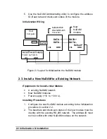
3.  Power off the NuDAM power supply of the existing RS-485 

network. 

4.  Power off the host computer. 
5.  Wire the power lines for the new NuDAM with the existing 

network.  Be careful about the signal polarity as wiring. 

6.  Wire the RS-485 data lines for the new NuDAM with the existing 

network.  Be careful about the signal polarity as wiring. 

7.  Wire to the input or output devices.  Refer to section 2.4 for 

illustrations.  

8.  Power on the host computer. 
9.  Power on the NuDAM local power supply. 
10.  Use the NuDAM administration utility to check entire network. 


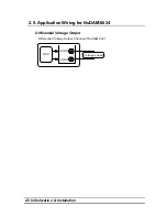
2. 4. Application Wiring for NuDAM-6021 

Differential Current Output 

+IOUT

Differential Current Output Channel of NuDAM 6021

DAC

-IOUT

Current Loading


Differential Voltage Output 

+VOUT

Differential Voltage Output Channel of NuDAM 6021

DAC

-VOUT

Voltage Loading


Summary of Contents for ND-6021

Page 1: ...ND 6021 ND 6024 Analog Input Modules User s Guide...

Page 2: ...ndirect special incidental or consequential damages arising out of the use or inability to use the product or documentation even if advised of the possibility of such damages This document contains pr...

Page 3: ...SE 3 1 3 2 SUMMARY OF COMMAND SET 3 4 3 3 SET CONFIGURATION 3 6 3 4 READ CONFIGURATION 3 9 3 5 READ MODULE NAME 3 10 3 6 READ FIRMWARE VERSION 3 11 3 7 RESET STATUS 3 12 3 8 SYNCHRONIZED SAMPLING 6024...

Page 4: ...22 HOST IS OK 3 33 4 DATA FORMAT 4 1 4 1 UNIT CONVERSION 4 1 4 2 ENGINEERING UNITS 4 1 4 3 PERCENT OF FSR 4 2 4 4 HEXDECIMAL FORMAT 4 3 4 5 SUMMARY OF DATA FORMAT 4 4 5 ANALOG OUTPUT CALIBRATION 5 1...

Page 5: ...A microprocessor is used to convert the digital command to digital value to send to DAC The DAC converts the digital value into analog form The analog output can be either voltage or current output Th...

Page 6: ...lure protection Internal watchdog timer for device failure protection Easy programming by software Easy installation and wiring Specifications of NuDAM 6021 Interface Interface RS 485 2 wires Speed bp...

Page 7: ...pply 10V to 30V Power consumption 1 0W Pin Definitions of ND 6021 Pin Signal Name Description 1 IOUT Positive Current Output Terminal 2 IOUT Negative Current OutputTerminal 3 VOUT Positive Voltage Out...

Page 8: ...ialization Installation A Look at ND 6021 Pin Assignment ND 6021 Y DATA G DATA R Vs B GND Analog Output Current Voltage 1 10 IOUT IOUT VOUT VOUT DEFAULT Code Output Range 30 31 32 0 20 mA 4 20 mA 0 10...

Page 9: ...uDAM 6024 What is NuDAM 6024 ND 6024 is a 4 channel bipolar analog signal output module I t receives the digital command from host computer through RS 485 network A microprocessor is used to convert t...

Page 10: ...ternal watchdog timer for device failure protection Easy programming by software Easy installation and wiring Specifications of NuDAM 6024 Interface Interface RS 485 2 wires Speed bps 1200 2400 4800 9...

Page 11: ...ositive 8 G DATA RS 485 series signal negative 9 R Vs Power supply 10V 30V 10 B GND Ground 11 VOUTA Positive Voltage Output A Terminal 12 AGND Negative Voltage Output A Terminal 13 VOUTB Positive Volt...

Page 12: ...ialization Installation A Look at ND 6024 Pin Assignment DI5 DI6 DGND VOUTD CGND VOUTC BGND VOUTB AGND VOUTA DI4 DI3 DI2 DI1 DI0 DEFAULT Y DATA G DATA R Vs B GND ND 6024 4 CH Analog Output Code Signal...

Page 13: ...Rv Micro Processor RS 485 Terminator EEPROM Watchdog Power Failure Supervisor Defalut Setting 1 bit Digital In Photo Isolators DAC 12 bits DC to DC Convertor Voltage Output Power Regulator 10V 30 V GN...

Page 14: ......

Page 15: ...ve drive name is C to Z Example 1 install to drive C A INSTALL C Example 2 install to drive F A INSTALL F 6 NuDAM Administration Utility will be installed in the directory C NUDAM 2 2 Initializing a B...

Page 16: ...Address ID is 00 Baud rate is 9600 bps Check sum disable Watchdog timer is disable Therefore the configuration of the host and the module can be easily set identically and initializing a module will...

Page 17: ...ing NuDAM network New NuDAM modules Power supply 10 to 30 VDC Installing Procedures 1 Configure the new NuDAM module according to the initialization procedure in section 2 2 2 The baud rate and check...

Page 18: ...k Be careful about the signal polarity as wiring 7 Wire to the input or output devices Refer to section 2 4 for illustrations 8 Power on the host computer 9 Power on the NuDAM local power supply 10 Us...

Page 19: ...2 5 Initialization Installation 2 5 Application Wiring for NuDAM 6024 Differential Voltage Output VOUT Differential Voltage Output Channel of NuDAM 6021 DAC VOUT Voltage Loading...

Page 20: ......

Page 21: ...with the modules Document Conventions The following syntax conventions describes the NuDAM commands in this manual Leading Code Leading Code is the first characteristic of the NuDAM command All NuDAM...

Page 22: ...ate checksum value Checksum LeadingCode Addr Command Data MOD 0x100 Example 1 checksum is disable User Command 012 CR Response 01400600 CR LeadingCode 01 Address 2 Command Read Configuration CR Carria...

Page 23: ...pends on versatile NuDAM command The response is composed with a few characteristics including leading code variables and carriage return for ending There are two categories of leading code for respon...

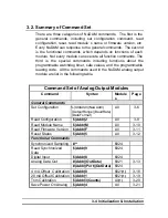
Page 24: ...grammable leading code All the commands used in the NuDAM analog output module are list in the following table Command Set of Analog Output Modules Command Syntax Module s Page General Commands Set Co...

Page 25: ...24 Change Command Leading Code Setting Addr 10 C1 C2 C3 C4 C5 C6 All 3 26 Set Host Watchdog Safety Value Addr 2 Flag TimeO ut SafeValue 6021 3 28 Addr 2 Flag TimeO ut SafeA SafeB SafeC SafeD 6024 Read...

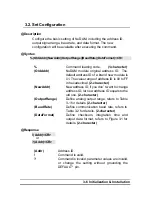
Page 26: ...he value range of address ID is 00 to FF in hexadecimal 2 character NewAddr New address ID if you don t want to change address ID let new address ID equals to the old one 2 character OutputRange Defin...

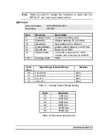
Page 27: ...address ID is 18 Hex 31 OutputRange Analog output range is 4 to 20 mA 06 BaudRate Baud rate is 9600 10 DataFormat 10 means a slew rate is 1 000 mA sec and checksum is disable CR Carriage return 0x0D C...

Page 28: ...10 Hexadecimal Slew Rate BitCode Voltage Current 0000 immediate change 0001 0 0625 V sec 0 125 mA sec 0010 0 125 V sec 0 250 mA sec 0011 0 250 V sec 0 500 mA sec 0100 0 500 V sec 1 000 mA sec 0101 1...

Page 29: ...ss ID OutputRange Current setting of analog voltage output refers to Table 3 1 for details BaudRate Current setting of communication baud rate refers to Table 3 2 for details DataFormat Current settin...

Page 30: ...mmand leading code Addr Address ID M Read module name Response Addr ModuleName CR or Addr CR Command is valid Command is invalid Addr Address ID ModuleName NuDAM module s name would be 6021 4 characte...

Page 31: ...dr F CR Command leading code Addr Address ID F Read module firmware version Response Addr FirmRev CR or Addr CR Command is valid Command is invalid Addr Address ID FirmRev NuDAM module s firmware vers...

Page 32: ...d leading code Addr Address ID 5 Reset Status Command Response Addr Status CR or Addr CR Command is valid Command is invalid Addr Address ID Status 0 It has not been reset since the last reset status...

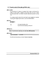
Page 33: ...ead Synchronized Data command to read the data and process it one by one For analog output module this command is only available to modules involving the digital input function such as NuDAM 6024 Synt...

Page 34: ...mmand leading code Addr Address ID 9 Read synchronized data Response Status DataIn CR or Addr CR Command is valid Command is invalid Status 0 Data has been sent at least once before 1 Data has been se...

Page 35: ...ng code Addr Address ID 8 Digital data input command Response DataIn 0000 CR or Addr CR Command is valid Command is invalid DataIn Value of digital input 2 character Example User command 308 CR Respon...

Page 36: ...g format Syntax Addr OutData CR 6021 Only Addr Port OutData CR 6024 Only Command leading code 1 character Addr Address ID 2 character Port A B C or D OutData Value of the analog output signal The unit...

Page 37: ...log output to be 4 mA at address 08H if the data format is configured as of FSR and 0 20mA output range 4mA 20mA x 20 00 User command 097FF CR Response CR The command sets the analog output to be 5 V...

Page 38: ...Code Response Addr CR or Addr CR Command is valid Command is invalid or no synchronized sampling command was issued Addr Address ID Example User command 060 CR Response 06 CR To perform the 4 mA cali...

Page 39: ...Function Code 20 mA calibration 1 character Response Addr CR or Addr CR Command is valid Command is invalid Addr Address ID Example User command 061 CR Response 06 CR To perform the 20 mA calibration...

Page 40: ...rrent Range 00 5F 0 to 95 counts increase Range A1 FF 95 to 1 counts decrease 1 count equals approximately 4 88 A or 2 44mV 4 88mV for ND 6024 Response Addr CR or Addr CR Command is valid Command is i...

Page 41: ...utput channel when system power ON Syntax Addr 4 CR Command leading code 1 character Addr Address ID 2 character 4 Function code of saving power on analog value 1 character Response Addr CR or Addr CR...

Page 42: ...n the start up output value only 6021 Syntax Addr 6 CR Addr 6 Port CR 6024 Only Command leading code 1 character Addr Address ID 2 character 6 Function code of last value readback 1 character Port Por...

Page 43: ...dr 8 CR Command leading code 1 character Addr Address ID 2 character 6 Function code of last value readback 1 character Response Addr Data CR or Addr CR Command is valid Command is invalid Addr Addres...

Page 44: ...ilure or watchdog failure Bit 2 Host watchdog is enable Bit 3 Host failure C1 Leading code 1 for read configuration status firmware version etc default is 1 character C2 Leading code 2 for read synchr...

Page 45: ...Command Set 3 25 Example User command 060 CR Response 0600 CR Command leading code setting is for module address ID is 06 current status is factory default setting...

Page 46: ...tus firmware version etc default is 1 character C2 Leading code 2 for read synchronize sampling digital output default is 1 character C3 Leading code 3 for change configuration default is 1 character...

Page 47: ...change leading code to A then use A06F to read firmware version of module on address 06 WARNING l We do not recommend users to change the default setting of leading code because it will confuse yours...

Page 48: ...meOut Host timeout value between this time period host must send Host is OK command to module otherwise module will change to safety state Range 01 FF 2 character One unit is 53 3 ms Firmware version...

Page 49: ...t value 0x12 18 18 53 3 959 ms Firmware Version 1 x 18 100 1800 ms Firmware Version 2 x 3F0 0x3F0 is hexadecimal Analog output value is 4 923 mA for 0 20mA Analog output value is 4 923 mA for 4 20mA A...

Page 50: ...safe state value 1 Enable host watchdog timer 12 Timeout value 0x12 18 18 53 3 959 ms Firmware Version 1 x 18 100 1800 ms Firmware Version 2 x 800 800 800 800 0x800 is hexadecimal Analog output value...

Page 51: ...or Addr CR Command is valid Command is invalid Addr Address ID range 00 FF Flag 0 Host watchdog timer is disable 1 Host watchdog timer is enable 1 character TimeOut Host timeout value Range 01 FF 2 c...

Page 52: ...923 mA for 0 20mA Analog output value is 4 923 mA for 4 20mA Analog output value is 2 462 V for 0 10 V User command 063 CR Response 06112800800800800 CR 06 Address ID 1 Host watchdog timer is enable 1...

Page 53: ...ule before timeout otherwise host watchdog timer enable module s output value will go to safety state output value Timeout value and safety state output value is defined in 3 14 Set Host Watchdog Time...

Page 54: ......
Page 55: ...e Range 3 Hexdecimal 4 2 Engineering Units The date is in engineering unit when the bit 1 and 0 of the configuration register are 00 The data string is composited by 6 characters Because the output of...

Page 56: ...d by 6 characters Because the output of ND 6021 is unipolar the value is always positive The value is unit less and depends on the output range setting too Set bit 1 and bit 0 of data format variable...

Page 57: ...is equivilant to 12 binary bits Because the output of ND 6021 is unipolar the maximum value of the digits is FFF H and the minimum value of the digits is 000 H As the output range is set to 0 20mA the...

Page 58: ...20 mA Eng Units 20 000 04 000 4 88 A 32 0 to 10 V Eng Units 10 000 00 000 2 442 mV Code Output Range Data Format Maximum Value Minimum Value Output Resolution 30 0 to 20 mA of FSR 100 00 000 00 4 88...

Page 59: ...git multimeter 2 A resistor 250 Accurary is 0 01 3 NuDAM Aministration Utility Calibration Procedure 1 Select output range to 0 20 mA or 4 20 mA 2 Put the resistor 250 to the NuDAM 6021 IOUT Pin 1 and...

Page 60: ...mmand with output value is 20 mA For example if the address is 0x03 then the command is 0320 000 8 Use Trim calibration Addr 3 Counts command to adjust until the output value to 5 V 20 mA 9 Send 20mA...

Reviews: