6
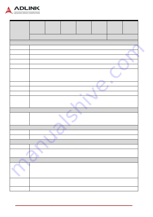
Specifications
I/O Interface
Display
6x DisplayPort (2 from CPU, 4 from MXM)
Ethernet
1x GbE (Intel® i219-LM), 3x GbE (Intel® i210-AT)
Serial Ports
1x RS-232/422/485, 1x RS-232
USB
6x USB 3.2 Gen1 x1 ports, 2x USB 2.0 ports
Audio
Mic-in, L/R speaker-out (6W + 6W) (Optional)
M.2
X
1x M.2 E key for 1630 or 2230 Wi-Fi/BT module
X
1x M.2 B key for 2242 or 2280 SATA storage module
X
1x M.2 M key for 2242 or 2280 SATA/PCIe x4 storage module
eSIM
Optional
DI/O
1x DI/DO with 4 in, 4 out
TPM 2.0
Yes
Expansion
2x PCIe Gen3 x4 expansion slots for full height, half length add-on card.
Each slot supports 25W power and additional Molex 4-pin power cable
(12V/1.5A and 5V/2A).
Storage
SATA
X
2x 2.5" SATA 6Gb/s external drive bays
X
2x SATA 6Gb/s signals via M.2 M & B key connectors
X
Intel® RST RAID Support
Physical
Dimensions
235 x 182 x 129mm (W x D x H, without foot pads)
Mounting
Optional wall-mount bracket
Power Supply
DC Input
DC 12V input (Molex DC-in jack)
AC Input
X
Optional: 240W (12V/20A) AC/DC adapter
X
Optional: 500W (12V/41.7A) AC/DC power supply unit
Environmental
Operating
Temperature
0°C to 50°C (W/MXM module except RTX-5000, W/SSD; w/add on card supported
operating temperature is 0°C to 70°C)
0°C to 40°C (W/MXM RTX-5000, W/SSD, w/add on card supported operating
temperature is 0°C to 70°C)
Storage
Temperature
-20°C to 70°C
Humidity
5% to 95%, non-condensing
Model
DLAP-
3200-
CFP1
DLAP-
3200-
CFP2
DLAP-
3200-
CFT1
DLAP-
3200-
CFT3
DLAP-
3200-
CFT5
DLAP-
3200-
CFP3
DLAP-
3200-
CFP5
DLAP-3200-CFP12*
DLAP-3200-CFP35*
Summary of Contents for DLAP-3200-CF Series
Page 8: ...viii List of Tables This page intentionally left blank ...
Page 10: ...x List of Figures This page intentionally left blank ...
Page 14: ...4 Introduction This page intentionally left blank ...
Page 21: ...Specifications 11 DLAP 3200 CF Figure 2 3 DLAP 3200 CF Left Side View 194 50 182 00 ...
Page 22: ...12 Specifications Figure 2 4 DLAP 3200 CF Right Side View 194 50 182 00 ...
Page 23: ...Specifications 13 DLAP 3200 CF Figure 2 5 DLAP 3200 CF Rear View 235 00 ...
Page 26: ...16 System Layout Figure 3 2 DLAP 3200 CF Rear Panel I O P N O ...
Page 54: ...44 System Layout This page intentionally left blank ...
Page 59: ...Getting Started 49 DLAP 3200 CF Left side screws ...
Page 60: ...50 Getting Started Right side screws ...
Page 62: ...52 Getting Started 3 Remove the 4 screws attaching the left drive bay to the chassis ...
Page 69: ...Getting Started 59 DLAP 3200 CF Right side screws ...
Page 70: ...60 Getting Started Left side screws ...
Page 71: ...Getting Started 61 DLAP 3200 CF Bottom screws ...
Page 85: ...Getting Started 75 DLAP 3200 CF 3 Remove the 8 screws attaching the BM cover to the chassis ...
Page 86: ...76 Getting Started 4 Remove the BM cover ...
Page 87: ...Getting Started 77 DLAP 3200 CF 5 Remove the fan ...
Page 94: ...84 Getting Started This page intentionally left blank ...
Page 140: ...130 BIOS Setup This page intentionally left blank ...
Page 150: ...140 Consignes de Sécurité Importante This page intentionally left blank ...


