


BIOS Setup
105
DLAP-3200-CF
C.4.3
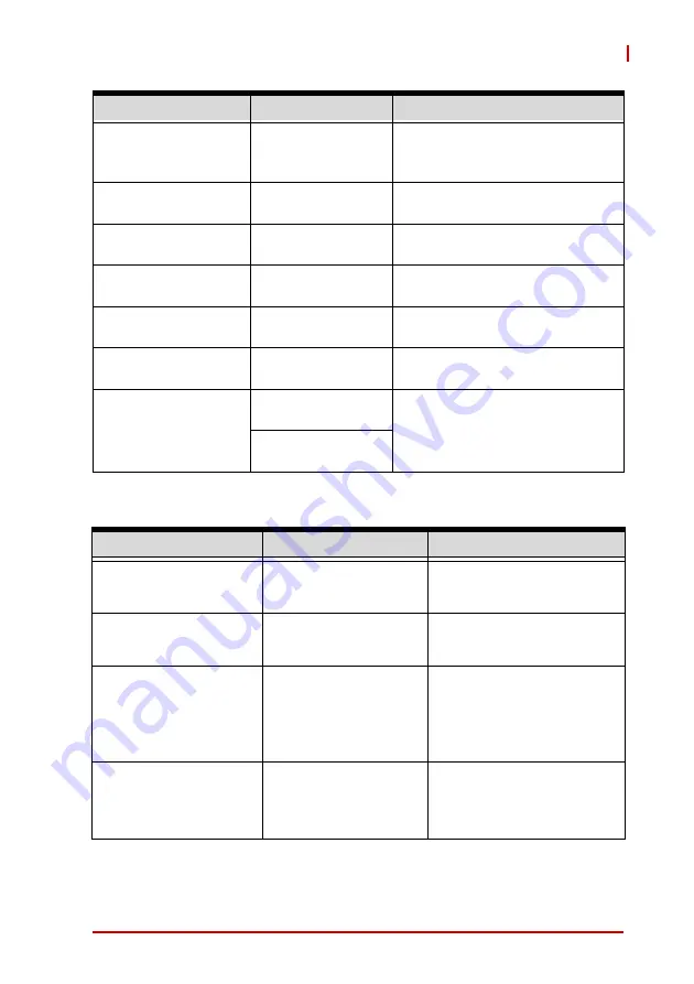
Advanced > Power Management
Data format and Color
Depth
VESA 24 bpp
JEIDA 24 bpp
JEIDA/vesa 18 bpp
Data format and Color Depth
select
LVDS Output Mode
Dual LVDS bus
Single LVDS bus
Single/Dual mode select
DE Polarity
Active High
Active Low
DE Polarity select
Vsync Polarity
Active High
Active Low
Vsync Polarity select
Hsync Polarity
Active High
Active Low
Hsync Polarity select
LVDS Backlight Mode BMC Mode
GTT Mode
Select LVDS Backlight control
function.
LVDS Backlight
Brightness
BMC Mode: 0-255
Default: 255
Set LVDS Backlight Brightness
Percentage.
The change takes effect
immediately.
GTT Mode: 0-100
Default 100
Feature
Options
Description
Power Management
Info only
Enable ACPI Auto
Configuration
Disabled
Enabled
Enables/Disables BIOS
ACPI Auto Configuration.
Enable Hibernation
Disabled
Enabled
Enables/Disables System
ability to Hibernate (OS/S4
Sleep State). This option
may not be effective with
some operating systems.
ACPI Sleep State
Suspend Disabled
S3 (Suspend to RAM)
Select the highest ACPI
sleep state the system will
enter when the SUSPEND
button is pressed.
Feature
Options
Description
Summary of Contents for DLAP-3200-CF Series
Page 8: ...viii List of Tables This page intentionally left blank ...
Page 10: ...x List of Figures This page intentionally left blank ...
Page 14: ...4 Introduction This page intentionally left blank ...
Page 21: ...Specifications 11 DLAP 3200 CF Figure 2 3 DLAP 3200 CF Left Side View 194 50 182 00 ...
Page 22: ...12 Specifications Figure 2 4 DLAP 3200 CF Right Side View 194 50 182 00 ...
Page 23: ...Specifications 13 DLAP 3200 CF Figure 2 5 DLAP 3200 CF Rear View 235 00 ...
Page 26: ...16 System Layout Figure 3 2 DLAP 3200 CF Rear Panel I O P N O ...
Page 54: ...44 System Layout This page intentionally left blank ...
Page 59: ...Getting Started 49 DLAP 3200 CF Left side screws ...
Page 60: ...50 Getting Started Right side screws ...
Page 62: ...52 Getting Started 3 Remove the 4 screws attaching the left drive bay to the chassis ...
Page 69: ...Getting Started 59 DLAP 3200 CF Right side screws ...
Page 70: ...60 Getting Started Left side screws ...
Page 71: ...Getting Started 61 DLAP 3200 CF Bottom screws ...
Page 85: ...Getting Started 75 DLAP 3200 CF 3 Remove the 8 screws attaching the BM cover to the chassis ...
Page 86: ...76 Getting Started 4 Remove the BM cover ...
Page 87: ...Getting Started 77 DLAP 3200 CF 5 Remove the fan ...
Page 94: ...84 Getting Started This page intentionally left blank ...
Page 140: ...130 BIOS Setup This page intentionally left blank ...
Page 150: ...140 Consignes de Sécurité Importante This page intentionally left blank ...


