


Troubleshooting
7-3
7-
Troubleshooting
Various problems can arise when configuring and using the
FCR200. This section is provided to help guide the user
through some of the basic methods of identifying faults in the
setup and configuration of the unit.
Most problems are found in the initial installation. In general,
it is wise to check all connections and review the configuration
before proceeding with further trouble analysis. Simplify the
installation if possible, reducing it to the most basic
configuration then adding elements one at a time and
verifying the operation at each step.
Indicators
The LED indicators on the FCR200 are useful for diagnosing
various problems.
•
The Power indicator turns on when power is applied to the
router. Lack of power indication suggests the unit being
turned off, a problem with the power supplied to the unit,
or an internal problem with the unit.
•
The Fault indicator is lit when the FCR200 detects a fault
condition. Faults can occur as a result of Power On Self
Test (POST) failure or operational failures. It is normal for
this indicator to flash on when the unit is powered up or
reset. If the fault indicator stays lit, contact customer
support.
•
The SCSI 1 indicator shows SCSI 1 activity when lit. This
should only occur briefly during power up or
configuration, and relatively often when the unit is
transferring data. If the SCSI indicator stays continually lit
without corresponding target device activity, it may
indicate a problem with the SCSI bus configuration.
Verify the SCSI bus configuration.
•
The SCSI 0 indicator shows SCSI 0 activity when lit. This
should only occur briefly during power up or
configuration, and relatively often when the unit is
transferring data. If the SCSI indicator stays continually lit
without corresponding target device activity, it may
indicate a problem with the SCSI bus configuration.
Verify the SCSI bus configuration.
Summary of Contents for FCR 200
Page 1: ...FCR 200 Operator Guide ...
Page 10: ...x Contents 62 9301 01 ...
Page 14: ...xiv Tables 62 9301 01 ...
Page 16: ...1 2 Introduction 62 9301 01 ...
Page 20: ...1 6 Introduction 62 9301 01 EN60950 IEC950 Product Safety VCCI Statement Japan ...
Page 22: ...2 2 Description 62 9301 01 ...
Page 32: ...2 12 Description 62 9301 01 ...
Page 34: ...3 2 Safety 62 9301 01 ...
Page 40: ...3 8 Safety 62 9301 01 ...
Page 42: ...4 2 Installation 62 9301 01 ...
Page 64: ...5 2 Understanding the Configuration 62 9301 01 ...
Page 72: ...5 10 Understanding the Configuration 62 9301 01 ...
Page 96: ...7 2 Troubleshooting 62 9301 01 ...
Page 102: ...7 8 Troubleshooting 62 9301 01 ...
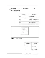
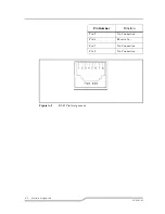
Page 103: ...A Ethernet Assignments RJ 11 Serial and RJ 45 Ethernet Pin Assignments A 3 ...
Page 104: ...A 2 Ethernet Assignments 62 9301 01 ...
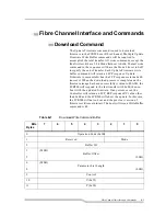
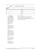
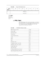
Page 108: ...B 2 Fibre Channel Interface and Commands 62 9301 01 ...
Page 114: ...B 8 Fibre Channel Interface and Commands 62 9301 01 ...
Page 115: ...C SCSI Interface and Commands SCSI Interface and Commands C 3 SCSI Inquiry Data C 3 ...
Page 116: ...C 2 SCSI Interface and Commands 62 9301 01 ...
Page 120: ...D 2 Addressing Structures and Operation 62 9301 01 ...
Page 126: ...D 8 Addressing Structures and Operation 62 9301 01 ...
Page 127: ...E Reference Standards Standards E 3 ...
Page 128: ...E 2 Reference Standards 62 9301 01 ...
Page 130: ...E 4 Reference Standards 62 9301 01 ...
Page 140: ...in 4 Index 62 9301 01 ...


