ADC ADE-75 Installation And Operation Manual Download Page 30

26

IMPORTANT

:  A strain relief  

must be

 used where the input wiring enters the oven assembly.

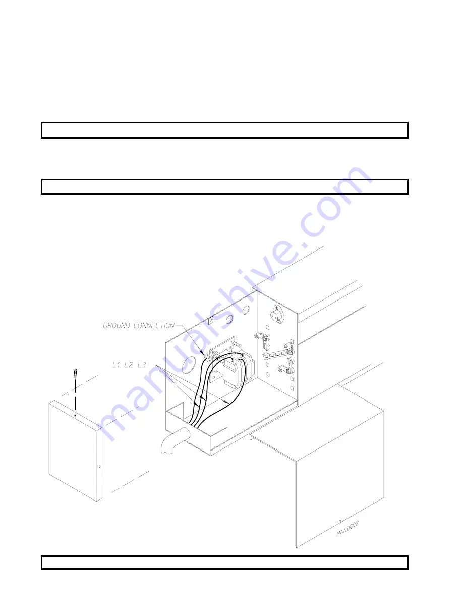
   b)  ELECTRICALLY Heated Models Only

The only electrical input connections to the dryer are the 3-phase (3 Ø) power leads (L1,L2,L3

and sometimes neutral) and ground. Single phase power for the control circuit and for any

single phase (1 Ø) motors (if present) is done internally to the dryer by the factory at the

oven contactor. No single phase (1 Ø) input connection is required on a 3-phase (3 Ø)

dryer.

CAUTION

:  The dryer


must be

 grounded.  A ground lug has been provided for this purpose.

Input connection wiring 

must be

 sized properly to handle the dryer's current draw.  This

information is printed on the dryers data label.

IMPORTANT

:  A separate circuit serving each dryer 

must be

 provided.

The electrical input connections are made at the electric oven contactor located inside the

assembly at the rear center upper section of the dryer.  The ground connection is made to a

copper lug also provided in this area.  To gain access, remove oven rear service cover.

Summary of Contents for ADE-75

Page 1: ...l the firedepartment Installation and service must be performed by a qualifiedinstaller serviceagencyorthegas supplier AVERTISSEMENT Assurez vous de bien suivre les instructions donn es dans cette not...

Page 2: ...d in a prominentlocationnearthedryer American Dryer Corporation products embody advanced concepts in engineering design and safety If this product is properly maintained it will provide many years of...

Page 3: ...ESUPERVISEDIFNEARDRYER S INOPERATION DRYER S SHOULDNEVERBELEFTUNATTENDEDWHILEINOPERATION CAUTION FOR YOUR SAFETY DONOT DRYMOPHEADSINTHEDRYER DONOTUSEDRYERINTHEPRESENCEOFDRYCLEANINGFUMES WARNING UNDER...

Page 4: ...n the equipment and or specified in the installation operator s manual included with the dryer Dryer s must not be installed or stored in an area where it will be exposed to water and or weather The w...

Page 5: ...NTS 10 UNPACKING SETTING UP 11 DRYER ENCLOSURE REQUIREMENTS 12 FRESH AIR SUPPLY 13 EXHAUST REQUIREMENTS 14 ELECTRICAL INFORMATION 19 GAS INFORMATION 27 STEAM INFORMATION 30 PREPARATION FOR OPERATION S...

Page 6: ...46 SECTION VII PROCEDURE FOR FUNCTIONAL CHECK OF REPLACEMENT COMPONENTS 47 MICROPROCESSOR 47 DIRECT SPARK IGNITION D S I SYSTEM 48 SECTION VIII REVERSING SPIN DWELL ADJUSTMENTS 49 SECTION IX TECHNICA...

Page 7: ...the number received and the number refused must be noted on the receipt 4 If you determine that the dryer was damaged after the trucker has left your location you should call the delivering carrier s...

Page 8: ...all your gas supplier from a neighbor s phone Follow the gas supplier s instructions f If you cannot reach your gas supplier call the fire department 4 Installation and service must be performed by a...

Page 9: ...ING Articles left in the dryer after the drying and cooling cycles have been completed can create a fire hazard 12 DO NOT operate steam dryers with more than 125 PSI steam pressure Excessive steam pre...

Page 10: ...7 21 5 7851 211 7 21 SVL PD EDU SECTION II SPECIFICATIONS COMPONENT IDENTIFICATION A SPECIFICATIONS For non reversing models A minimum of 3 4 pipe must be supplied to the gas inlet for each dryer Cont...

Page 11: ...7 Specifications ADG 75D Gas ADE 75 Electric ADS 75 Steam NOTE ADC RESERVES THE RIGHT TO MAKE CHANGES IN SPECIFICATIONS AT ANY TIME WITHOUT NOTICE or OBLIGATION...

Page 12: ...RYER FRONT VIEW Illus No Description 1 Controls 2 Control top access Door Assembly 3 Main Door Assembly 4 Lint Compartment Area lint screen located behind door 5 Data Label and Installation Label loca...

Page 13: ...8 Compressed Air Supply Inlet behind Electric Service Relay Box for steam units ONLY 3 Electric Service Relay Box 4 Tumbler Bearing Mount Assembly 5 Idler Bearing Mount Assembly 6 Blower Motor Assembl...

Page 14: ...loor area that the dryer is to rest on 2 The dryer must not be installed or stored in an area where it will be exposed to water and or weather 3 The dryer is for use in noncombustible locations 4 Prov...

Page 15: ...tion slightly lower ALL four 4 leveling legs so that the dryer will slide on the legs instead of the base frame To increase bearing life and improve efficiency the dryer should be tilted slightly to t...

Page 16: ...sarelocatedabovethedryers aminimumof 18 inchesabovethedryerconsole module isrequired Dryersmaybe positionedsidewalltosidewallhowever a1 16 inchminimum allowanceisrequiredbetweendryers orwall foreaseof...

Page 17: ...of 1 1 2 square feet is required for each dryer To compensate for the use of registers or louvers used over the openings this make up air must be increased by approximately thirty three percent 33 Mak...

Page 18: ...re used the cross sectional area of the duct work must beincreased ALL duct workshouldbesmoothinsidewithnoprojectionsfromsheetmetalscrewsorotherobstructionswhichwill collectlint Whenaddingducts theduc...

Page 19: ...ting Where possible it is suggested to provide a separate exhaust duct for each dryer The exhaust duct should be laid out in such a way that the duct work travels as directly as possible to the outdoo...

Page 20: ...should be installed at strategic points in the exhaust duct work for periodic inspection and clean out of lint from the ductwork NOTE Wheretheexhaustductpassesthroughawall ceiling orroofmadeofcombust...

Page 21: ...irty 30 feetandeach45 elbowisequivalenttoanadditional fifteen 15 feet IMPORTANT Forextendedductworkruns thecrosssectionareaoftheductworkcanonlybe increasedtoanextent Maximumproportionalductworkrunscan...

Page 22: ...18...

Page 23: ...NT Failure to comply with these codes or ordinances and or the requirements stipulated in this manual can result in personal injury or component failure NOTE Component failure due to improper installa...

Page 24: ...make changes in specifications at any time without notice or obligation ADG 75 Gas ADS 75 Steam ELECTRICAL SERVICE SPECIFICATIONS PER DRYER IMPORTANT 208 VAC AND 230 240 VAC ARE NOT THE SAME WHEN ORD...

Page 25: ...ANTY NOTE ADC reserves the right to make changes in specifications at any time without notice or obligation APPROX AMP DRAW IMPORTANT 3 phase figures shown are for a 3 wire service ONLY ADE 75 Electri...

Page 26: ...tal connection all the way to the electrical ground If there are any non metallic interruptions such as a meter pump plastic rubber or other insulating connectors they must be jumped out with no 4 cop...

Page 27: ...Hookup NON REVERSING MODELS ONLY The electrical connections on ALL three phase 3 gas and steam dryers are made into the rear service box located at the upper left area of the dryer Electrical connect...

Page 28: ...1 input connection is required on a three phase 3 dryer For gas and steam dryers manufactured for operation at three phase 3 the electrical connections are made at the power distribution block located...

Page 29: ...er can be hard wired directly to the service breaker panel In all cases a strain relief must be installed where the wiring enters the dryer The only electrical input connections to the dryer are the 3...

Page 30: ...gle phase 1 input connection is required on a 3 phase 3 dryer CAUTION The dryer must be grounded A ground lug has been provided for this purpose Input connection wiring must be sized properly to handl...

Page 31: ...ly as noted can cause irreparable damage to the gas valve VOIDING THE WARRANTY WARNING FIRE or EXPLOSION COULD RESULT 1 GAS SUPPLY The gas dryer installation must meet the American National Standard N...

Page 32: ...blocked open so that the gas pressure must be regulated upstream of the dryer The pressure measured at each gas valve pressure tap must be a consistent 11 0 inches water column There is no regulator...

Page 33: ...pipe size supply line to the dryer is 3 4 N P T For ease in servicing the gas supply line of each dryer must have its own shut off valve The size of the main gas supply line header will vary dependin...

Page 34: ...tal amount of ALL the appliance BTU s being supplied IMPORTANT The dryer and its individual shut off valve must be disconnected from the gas supply piping system during any pressure testing of that sy...

Page 35: ...supply piping to the dryer must include a 12 inch rise along with a drip trap and check valve This will prevent any condensate from entering the steam coil c Flexible hoses or couplings must be used T...

Page 36: ...ns of steam supply piping should be pitched 1 4 inch for every one 1 foot back towards the steam supply header causing the condensate in the line to drain to the header Install a bypass trap in any lo...

Page 37: ...ectric service relay box a Air Requirements b Air Connection Air connection to system 1 8 inch N P T c No air regulator or filtration is provided with the dryer External regulation filtration of 80 ps...

Page 38: ...ding instant heat to start the drying process When the damper is closed ambient air is drawn directly into the tumbler allowing a rapid cool down Diagram 2 Diagram 1 shows the damper in the heating op...

Page 39: ...d and adjusted prior to shipping at 80 PSI steam damper operation must be checked before the dryer is put into operation Refer to page 33 for instructions to check steam damper operation If steam damp...

Page 40: ...ed and adjusted at the factory prior to shipping However each sail switch adjustment must be checked to assure that this important safety control is functioning see page 37 for Sail Switch Adjustment...

Page 41: ...nternal diagnostics If ignition is not established the heat circuit in the DSI module will lock out until it is manually reset To reset the DSI system open and close the main door and restart the drye...

Page 42: ...oning properly IMPORTANT The dryer basket tumbler is treated with a protective coating ADC suggests tumbling old clothes or material in the basket tumbler using a mild detergent to remove the protecti...

Page 43: ...adjustable in the Manual timed Mode b Dual Timer Models 1 Both dwell stop and basket tumbler spin time are adjustable see illustration on page 48 9 Check to insure that ALL set screws i e tumbler dri...

Page 44: ...switch or the circuit breaker 2 Discontinue the heat supply a GAS MODELS discontinue the gas supply 1 SHUT OFF external gas supply shut off valve 2 SHUT OFF internal gas supply shut off valve located...

Page 45: ...al number so that your inquiry is handled in an expeditious manner B PARTS 1 Replacement parts should be purchased from the distributor from whom the ADC equipment was purchased If the distributor can...

Page 46: ...0199 If the distributor cannot be contacted or is unknown warranty information can be obtained from the factory by contacting the ADC Warranty Department at 508 678 9000 NOTE WhenevercontactingtheADCf...

Page 47: ...are not damaged in transit Damage claims are the responsibility of the shipper IMPORTANT Noreplacements creditsorrefundswillbeissuedformerchandisedamagedin transit 5 ALLreturnsshouldbeshippedtotheADC...

Page 48: ...ZARD WARNING KEEP DRYER AREA CLEAR AND FREE FROM COMBUSTIBLE MATERIALS GASOLINE andOTHERFLAMMABLEVAPORSand LIQUIDS NOTE Suggestedtimeintervalsshownareforaverageusagewhichisconsideredsix 6 toeight 8 op...

Page 49: ...ove lint accumulation in customer furnished exhaust duct work system and from dryers internal exhaust ducting NOTE THEACCUMULATIONOFLINTINTHEEXHAUSTDUCTWORKCAN CREATEAPOTENTIALFIREHAZARD NOTE DONOTOBS...

Page 50: ...hut off valves orifices and grounding connections Motor and drive belts should be examined Cracked or seriously frayed belts should be replaced Tighten loose V belts when necessary Complete operationa...

Page 51: ...ssor computer board reestablish power to the dryer b Start the drying cycle c Verify that the motor s and the heat indicator dots in the microprocessor computer L E D display are on Refer to the illus...

Page 52: ...conds pre perge time d The module s indicator light will then turn green The gas valve will be energized and the ignitor probe will spark for approximately 8 seconds The burner flame should now be est...

Page 53: ...ich is located in the upper rear area of the dryer Both the dwell stop time and basket tumbler spin time are adjustable by mode selection switches located on the electronic timer as noted in the illus...

Page 54: ...ting American Dryer Corporation certain information is required to insure proper service parts information from American Dryer This information is on the data label located on the inside of the contro...

Page 55: ...ular model 4 TYPE OF HEAT The type of heat describes the type heat for your particular dryer gas either natural gas or liquid propane L P or steam 5 HEAT INPUT for GAS DRYERS This describes the heat i...

Page 56: ...ng as the fuse being replaced The information provided should not be misconstrued as a handbook for use by an untrained person in making repairs WARNING ALL SERVICE and TROUBLESHOOTING SHOULD BE PERFO...

Page 57: ...ING YELLOW Z 62 CONDENSATION ON MAIN DOOR GLASS AA 62 DRYER SCRAPING NOISE AT BASKET TUMBLER AREA BB 62 EXCESSIVE NOISE OR VIBRATION CC 62 63 TIMER MODELS DRYER DOES NOT START A B 63 DRIVE MOTOR REVER...

Page 58: ...ssor controller computer motor indicator dot and relay output L E D indicator dots are on but motor output L E D indicator is off a Failed microprocessor controller computer C Drive motor Reversing Mo...

Page 59: ...Both drive motor and blower impellor fan motor Reversing Models ONLY not operating does not start microprocessor computer motor indicator dots and relay output L E D light emitting diode indicators a...

Page 60: ...icator is off 1 Fault open circuit in main door lint drawer switch circuit a Main door not closed all the way b Main door switch is out of proper adjustment c Failed lint main door switch d Broken wir...

Page 61: ...a cycle microprocessor controller computer buzzer tone sounds for 5 seconds and then the L E D returns to FILL 1 Loose connection somewhere in the main power circuit to the microprocessor controller...

Page 62: ...iction in the exhaust 3 No exhaust air flow a Failed impellor fan blower b Fault in blower impellor fan motor circuit for Reversing Models ONLY 2 Failed burner hi limit 3 Failed lint chamber sensor br...

Page 63: ...del electric oven contactor or Steam Model steam damper system 3 way micro valve GAS MODELS 1 Fault in Direct Spark Ignition system a Spark Probe sparks but no ignition and DSI module LOCKS OUT red L...

Page 64: ...mechanical motor b Steam damper stuck in closed position check for obstruction W Dryer operates but is taking too long to dry 1 Exhaust duct work run is too long or is undersized back pressure cannot...

Page 65: ...fan blower is rotating in the wrong direction only for 3 Models ONLY e Burner orifice size D M S drill material size too large for application i e high elevation 3 Sail switch is fluttering a Restrict...

Page 66: ...processor temperature sensor calibration is inaccurate 10 Failed lint chamber hi heat switch thermostat opens at incorrect temperature 11 Microprocessor temperature sensor covered with lint NOTE Lint...

Page 67: ...r improperly installed duct work 2 Back draft damper is sticking in the partially closed position BB Scraping noise at basket tumbler area 1 Check for obstruction caught in basket tumbler wrapper area...

Page 68: ...ll the way b Main door switch is out of proper adjustment c Failed main door switch d Broken connection wire somewhere in the main door switch circuit 4 Failed push to start relay 5 Failed 24 VAC step...

Page 69: ...ut on internal overload protector a Motor air vents clogged with lint b Low voltage to motor c Failed motor d Failed blower impellor fan out of balance G Both drive motor and blower impellor fan motor...

Page 70: ...as failed b Sail switch damper is not closing or is fluttering 1 Lint screen is dirty 2 Restriction in the exhaust 3 No exhaust air flow a Failed impellor fan blower b Fault in blower impellor fan mot...

Page 71: ...Failed gas valve b Hot surface ignitor glows but burner goes off right away 1 Flame probe assembly is out of adjustment or has failed 2 Sail switch is fluttering a Lint screen is dirty b Restriction...

Page 72: ...ticking partially closed b Restriction obstruction in duct work 1 Check duct work from the dryer all the way to the outdoors 3 Insufficient make up air 4 Impellor fan blower is rotating in the wrong d...

Page 73: ...irection only for 3 Models ONLY 5 Failed electric element s 6 Sail switch is fluttering a Restriction in the exhaust b Sail switch is not adjusted properly STEAM MODELS 1 Low steam pressure 2 Insuffic...

Page 74: ...e too large for application i e high elevation L Condensation on main door glass 1 Too long undersized or improperly installed duct work 2 Back draft damper is sticking in the partially closed positio...

Page 75: ...djustment bolts hardware are loose 5 Failed basket tumbler support 6 Loose motor mount 7 Failed idler basket tumbler or blower drive bearings 8 V belts too tight or too loose 9 Bearing set screws eith...

Page 76: ...ADC113035 1 03 06 98 50 2 03 17 98 250 3 05 05 98 250 4 06 24 98 500 5 10 27 98 250 6 12 07 98 1 000...

Reviews: