150-319-205-05, Issue 5
Loopback Operation
ELU-319 List 5E and List 6E
January 26, 2000
43
L
OOPBACK
T
EST
P
ROCEDURES
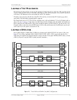
The following sections provide step-by-step test procedures for the ELU-319 as a function of the loopback option
selected. These procedures allow verification of the integrity of the HDSL channels at every module location as
well as the G.703 channels to the customer and the local G.703 interface.
If trouble is encountered on the ELU-319 List 5E G.703 interface, verify that the ELU is making a positive
connection with its mounting assembly (shelf) connector.
The transmit and receive E1 G.703 ports have splitting access jacks and miniature, 210-series, bridging jacks as
shown in
Figure 1 on page 6
. Connecting one cable between the two bridging jacks and another between the two
SPAN jacks splits the XMT and RCV and creates metallic loopbacks towards both the G.703 and the ELU-319.
If separate plugs are inserted into both SPAN jacks with the other end disconnected, the BRG jacks can be used
to send and receive test patterns towards the G.703.
L
OOPBACK
O
PERATION
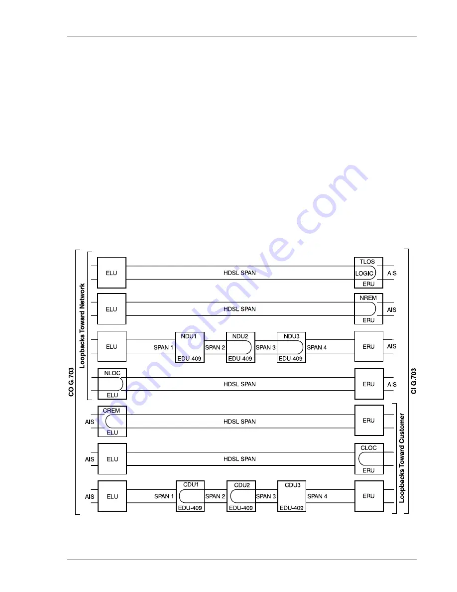
The complete family of loopbacks that a HiGain system equipped with the EDU-409 can execute is shown in
Figure 23
. Six of those loopbacks, NDU1, NDU2, NDU3; CDU1, CDU2, CDU3 occur in the doubler. The
loopbacks can be initiated from the ELU RS-232 craft port, the ELU front-panel MODE and SEL buttons, or from
a family of Special Loopback (SPLP) inband loopback commands.
Figure 23.
Non-doubler and Doubler Loopback Configurations

