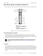
Product Description
150-319-205-05, Issue 5
8
January 26, 2000
ELU-319 List 5E and List 6E
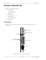
Front Panel Display
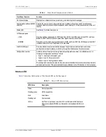
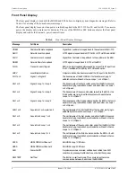
The front panel display is used with the MODE and SEL buttons to display system diagnostic messages. Refer to
Table 6
for a listing of the four-character messages.
The front panel display turns on when power is initially applied to the ELU-319 List 5E and List 6E. To conserve
power, the display only remains on for 4 minutes. The use of the MODE or SEL buttons activates the front panel
display and restarts the 4-minute, power-control timer.
Table 6.
Front Panel Display Messages
Message
Full Name
Description
CREM
Customer Remote Loopback
Signal from customer is looped back to the customer at ELU-319.
NLOC
Network Local Loopback
G.703 signal is looped back to G.703 at ELU-319 List 5E and List 6E.
CLOC
Customer Local Loopback
Signal from Customer is looped back to the customer at the ERU.
NREM
Network Remote Loopback
G.703 signal is looped back to G.703 at the ERU.
TLOS
Transmit Loss Of Signal
ERU is in a logic loopback state caused by a loss of its E1 input from
the CI, if enabled at the ERU by its TLOS switch option.
LBPV
Local Bipolar Violation
A bipolar violation has been received at the E1 input to the ELU-319.
SIG 1 or 2
Signal 1 or Signal 2
The transceivers of the ELU, ERU or first doubler are trying to
establish contact with each other on Loops 1 or 2 of Span 1.
S2L1 or 2
Signal 2 Loop 1 or Loop 2
The transceivers of the first doubler and either the ERU or second
doubler are trying to establish contact with each other on Loops 1
or 2 of Span 2.
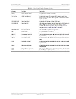
S3L1 or 2
Signal 3 Loop 1 or Loop 2
The transceivers of the second doubler and either the ERU or the
third doubler are trying to establish contact with each other on
Loops 1 or 2 of Span 3.
S4L1 or 2
Signal 4 Loop 1 or Loop 2
The transceivers of the third doubler and either the ERU or the fourth
doubler are trying to establish contact with each other on Loops 1
or 2 of Span 4.
ACQ 1 or 2
Acquisition 1 or Acquisition 2
The multiplexers of the ELU and ERU or first doubler are trying to
establish synchronization over Loops 1 or 2 of Span 1.
A2L1 or 2
Acquisition 2 Loop 1 or 2
The multiplexers of the first doubler and either the ERU or second
doubler are trying to establish synchronization with each other on
Loops 1 or 2 of Span 2.
A3L1 or 2
Acquisition 3 Loop 1 or 2
The multiplexers of the second doubler and either the ERU or third
doubler are trying to establish synchronization with each other on
Loops 1 or 2 of Span 3.
A4L1 or 2
Acquisition 4Loop 1 or 2
The multiplexers of the third doubler and either the ERU or fourth
doubler are trying to establish synchronization with each other on
Loops 1 or 2 of Span 4.
H1ES
HDSL CRC Error Channel 1
ELU HDSL Loop 1 CRC error.
H2ES
HDSL CRC Error Channel 2
ELU HDSL Loop 2 CRC error.
ACO
Alarm CutOff
A system alarm has occurred, and has been retired to an ACO
condition, by pressing the SEL button on the ELU front panel.
SELF TEST
Self Test
The ELU is in a self-test mode. This occurs when there is no
communication between the ELU and the EDU/ERU.

