
150-319-205-05, Issue 5
System Alarms
ELU-319 List 5E and List 6E
January 26, 2000
41
S
YSTEM
A
LARMS
Table 18
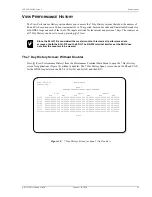
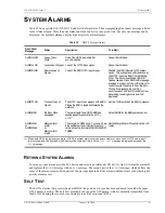
lists possible ELU-319 List 5E and List 6E alarm states. The accompanying front panel message is listed
in the Alarm column. More than one alarm condition can exist at any given time, but only one message can be
displayed. For multiple alarms, only the highest priority alarm displays.
R
ETIRING
S
YSTEM
A
LARMS
To retire a system alarm, press the SEL button and execute an Alarm Cut Off (ACO). An ACO turns the alarm off
and replaces the
ALRM
message with an
ACO
message. The second part of the
ALRM
message, which defines the
cause of the alarm, remains. Both parts of the message remain until the alarm condition clears or another higher
priority alarm occurs.
S
ELF
T
EST
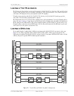
The Self Test mode that occurs when both HDSL loops are not in sync has been enhanced to include the input
G.703 transceiver chip. The Self Test procedure can cause the AIS pattern, which is normally transmitted from
the ELU-319 during these out of sync intervals, to exhibit occasional BPVs.
Table 18.
HDSL System Alarms
Front-Panel
Message
Alarm
Description
To inhibit:
ALRM LOSW
Loss of Sync
Word
(1)
(1) When both HDSL loops lose sync word (LOSW), a system alarm condition exists. However, since the ELU-319 enters a self
test cycling mode, the front panel LED lights yellow instead of red, and the
SELF TEST
message is displayed instead of the
ALRM
message.
One of the HDSL loops has lost
synchronization.
Cannot be inhibited.
ALRM LLOS
Local Loss of Signal Loss of the G.703 input signal.
Cannot be inhibited.
ALRM RLOS
Remote Loss of
Signal
Loss of the ERU G.703 input signal.
Disable the RDA (Remote G.703 Alarm)
option. This prevents an LOS condition at
the G.703 input to a ERU from activating
Pin H. The front panel Status LED still
flashes red and the ALRM RLOS message
displays to alert you of the LOS state. LOS
is sent toward the network from the ELU.
This option prevents the common
occurrences of a CPE LOS condition from
generating recurring alarms and AIS
payloads.
ALRM TLOS
Transmit Loss of
Signal
The G.703 input is not present at the ERU.
Places the ERU in loopback towards the
network.
Set the TLOS switch at the ERU to disable.
ALRM BER
Bit Error Rate
exceeded
The combined E1 and HDSL BER has
exceeded set threshold limits of 10
-6
or 10
- 7
.
Select NONE for the BER system option.
ALRM MAL1
or
ALRM MAL2
Margin Alarm
Loop1
or
Margin Alarm
Loop2
The margin on HDSL Loop 1 or Loop 2 has
dropped below the minimum threshold
value set by the terminal MARGIN ALARM
THRES.
Set the Margin Alarm Threshold option to 0
(zero).