
Product Description
150-319-205-05, Issue 5
10
January 26, 2000
ELU-319 List 5E and List 6E
ELU-319 L
IST
5E
AND
L
IST
6E C
ARD
C
ONNECTOR
Figure 2
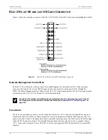
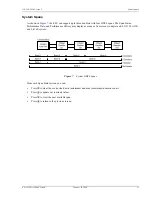
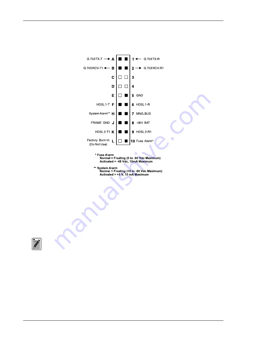
shows the card-edge connector of the ELU-319 List 5E and List 6E. Active pins are highlighted in black.
Figure 2.
ELU-319 List 5E and List 6E Card-Edge Connector
Network Management Control Bus
The ELU-319 List 5E and List 6E provides a Network Management Control Bus on Pin 7 of the card-edge
connector. This allows the various ADC Management System protocols to manage the ELU through the
HMU-319 HiGain Management Unit. Whenever the ELU-319 is under management, the
MNGD
message displays
periodically on the ELU-319 List 5E and List 6E front panel display.
Fuse Alarm
Pin 10 on the card-edge connector is a Fuse Alarm that is driven to -48 V whenever its onboard fuse opens. It
emulates the function of the Fuse Alarm output from Pin 10 on normal, high-density (HD) repeaters. Pin 10 is
connected to Pin 5 of the 1184 Alarm Card (Slot 1 in the HD shelf) and causes the 1184 Fuse ALM LED to light
when the Pin 10 signal is activated. Its normally floating output must never be driven above ground or below
-80 V. It can sink a current of 10 mA. The ELU-319 does not support the BPV function (Pin E) of normal HD
repeaters.
Some ELU-319 List 5E and List 6E features are affected when it is under management. Consult
the management unit practice for further information (see
“Appendix B - Product Support” on
page 45
).