ACV BMV1 Assembly And Operating Instructions Manual Download Page 11

GB

F

11

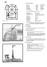
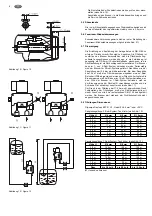
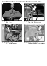
2.9  Oil connection to the burner

The oil hoses mounted onto the oil pump can be installed to the left
or right using (see fig. 13).

Attention: Remove the plugs form the oil hoses. With connec-

tion to the oil filter, pay attention to the arrow  mar-
king on the connection end of the hoses.

–  Hose connection (connection nut) 3/8” with grommet. 

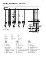
2.10 Electrical connection

With the electrical installation, the relevant CE guidelines as well
as the requirements of the local power utility company are to be
observed. S1, which is a an all-pole power circuit breaker accor-
ding to with min. 3 mm contact opening, is to be used as the main
switch. The connection cable must be wired with a Euro-plug (plug
component) 7-pole according to DlN 4791 and in accordance with
the circuit diagram. 
The connection is to be produced by plugging the connection
cable with the 7-pole boiler Euro-plug (plug component) and the 
7-pole burner Euro-plug (socket component) together. The burner
is delivered with a Euro-plug (socket component) as standard.

Attention: Check the Euro-plug (plug component) for proper

wiring.

2.11 General inspections

Attention: Before initial operation of the burner, the following

inspections are to be carried out:

- ls the mains voltage connected? 
- ls the oil supply guaranteed? 
- Have the stoppers been removed from the oil hoses and are 

the oil hoses connected properly? 

- ls the combustion air supply guaranteed?
- Has the burner been properly installed and are the boiler doors

closed? 

- ls the boiler filled with water ? 
- Are the boiler and the exhaust gas duct sealed tight?

3.  Initial operation and maintenance

For initial operation of the burner, all necessary switches and con-
trollers must be switched on. 
lf there is voltage at the burner and oil preheater, the green indica-
tor lamp lights up and the heating of the oil preheaters begins. The
heating up time can last up to 2 minutes. After the starting tempe-
rature has been reached, the motor starts and the ignition is swit-
ched on. After expiration of the preliminary venting time, the sole-
noid valve opens, the heating oil supply is released, and a flame is
formed. lf, with the first initial operation, the oil pump does not
deliver heating oil within the safety time, then a malfunction shu-
toff occurs.
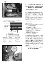
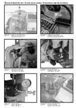
By resetting the automatic oil firing unit, burner start can be repea-
ted. Venting the oil pump and the oil line system must be carried
out via the manometer connection of the oil pump 
(see fig. 15).

Attention: The oil pump may not be operated without heating

oil for longer than 5 minutes, provided that there is
oil in the pump before initial operation.

2.9  Raccordement des fioul au brûleur

Les flexibles montés sur la pompe à fioul peuvent passer à droite
ou à gauche (Cf. fig. 13).

Attention: Retirer les embouts d’obstruction de flexibles.

Lors du raccordement au filtre à fioul, observer
impérativement la flèche marquée à  l’extrémité des
tuyaux.

–  Raccord de tuyaux femelle 3/8” avec bague bicône. 

2.10 Raccordement électrique

L’installation électrique doit être effectuée conformément
aux prescriptions normalisées CE ainsi qu’aux exigences des
entreprises locales d’alimentation en électricité. Pour l’interrupteur
principal  S1, utiliser un commutateur en charge conforme, sur
tous les pôles, avec au minimum 3 mm d’intervalle de coupure. Le
câble de raccordement doit être raccordé dans la fiche Euro à 7
pôles conforme aux normes DlN 4791 et en respectant le schéma
de connexion.

Attention: Vérifier si la prise européenne (mâle) est câblée 

correctement.

2.11 Contrôles généraux

Attention: Avant de mettre le brûleur en marche, il convient 

de procéder aux vérifications suivantes:

- La tension de secteur est-elle là?
- L’alimentation en fioul est-elle correcte? 
- Les bouchons d'obstruction des flexibles sont-ils enlevés, 

et les flexibles sont-ils correctement raccordés? 

- L’arrivée d’air de combustion fonctionne-t-elle? 
- Le brûleur a-t-il été monté correctement, et la porte de la

chaudière est-elle fermée? 

- La chaudière est-elle remplie d’eau? 
- La chaudière et les conduites des gaz de combustion 

sont-elles étanches?

3.

Mise en service et entretien

Pour la mise en service du brûleur, tous les interrupteurs et les
régulateurs doivent être enclenchés. Lorsque le brûleur et le
réchauffeur sont sous tension, la lampe témoin vert s'allume et le
réchauffeur commence à chauffer. Le temps de chauffe peut durer
jusqu'à 2 minutes. Une fois la température de départ atteinte, le
moteur se met en marche et l'allumage se déclenche. Une fois le
temps de pré-ventilation écoulé, l'électrovanne s'ouvre, l'arrivée
du fioul est dégagée, le fioul s'enflamme. Lors de la première mise
en service, si la pompe à fioul n'amène pas de fioul durant le
temps de sécurité, l'appareil se met hors service. On peut remett-
re le brûleur en marche en déverrouillant le dispositif d'allumage
automatique. 
L'aération de la pompe à fioul et du système de canalisation se fait
par le raccordement du manomètre de la pompe
(Cf. fig. 15).

Attention: La pompe fioul ne doit pas être actionnée plus de 

5 min. sans fioul, à condition qu'il y ait du fioul 
dans la pompe avant la mise en service.

Summary of Contents for BMV1

Page 1: ...2 Nozzle connection cover 3 Connection plug 4 Flange 5 Burner pipe 6 Ignition unit 7 Ignition cable 8 Oil pump 9 Suction connection 10 Return flow connection 11 Motor capacitor 12 Motor 13 Oil pressur...

Page 2: ...ahre Wir weisen darauf hin dass die Montage Inbetriebnahme und Wartung von einem Fachbetrieb ausgef hrt werden muss Die hier vorliegende Montage und Betriebsanleitung enth lt hierzu wichtige Informati...

Page 3: ...ns partir de la date d achat date de la fac ture Nous attirons l attention sur le fait que le montage la mise en service et l entretien devront tre ex cut s par une entreprise sp cia lis e Les pr sent...

Page 4: ...worden und beziehen sich auf eine H he von ca 100 m ber NN und eine Raumtemperatur von ca 20 C Der in der Praxis erreichbare ldurchsatz ist abh ngig vom Anfahrwiderstand des W rmeerzeugers Der Anfahrw...

Page 5: ...370 w 350 h 454 mm Transport weight 13 5 kg 1 Caract ristiques techniques 1 1 Puissance du br leur Type D bit de fioul Puissance du br leur BMV1 1 3 3 8 kg h 16 45 kW BMV2 3 0 5 5 kg h 36 65 kW lndica...

Page 6: ...tage des Brenners Serviceschraube l sen siehe Abb 8 und den Flansch mit Brennerrohr abnehmen Den Flansch inklusive dem Brennerrohr mit 4 M8 Schrauben am Heizkessel befestigen Serviceschraube oben posi...

Page 7: ...d be hot 1 7 Composants du br leur Moteur ACC EB 95 C 28 2 Condensateur Arcotronics 3 F 400 V DB Pompe Danfoss BFP 21 L3 Bobine magn tique Danfoss 071G0051 R chauffeur de fioul Danfoss FPHB 5 Unit d a...

Page 8: ...m Betrieb mit lf rderpumpe oder wenn der ltank h her liegt als die Brennerpumpe mu der Brenner im 1 Rohr System betrieben wer den Wird der Brenner im 1 Rohr System betrieben mu an der Brennerpumpe der...

Page 9: ...doit tre amen e suffisamment pr s du br leur pour que les flexibles puissent tre raccord s sans con traintes Dans la conduite c t aspiration monter un filtre fioul muni d un robinet fermeture rapide...

Page 10: ...und Regler eingeschaltet werden Wenn die Spannung am Brenner und lvorw rmer anliegt leuchtet die gr ne Kontrolleuchte und die Aufheizung des lvorw rmers beginnt Die Aufheizzeit kann bis zu 2 min betr...

Page 11: ...he oil pump see fig 15 Attention The oil pump may not be operated without heating oil for longer than 5 minutes provided that there is oil in the pump before initial operation 2 9 Raccordement des fio...

Page 12: ...chuss und muss grunds tzlich nachreguliert werden Die ben tigte Luft menge wird anhand von Russbild und CO2 Messungen ermittelt Die Einregulierung erfolgt vorzugsweise mit der Stellschraube der Luftdr...

Page 13: ...br leur Pour obtenir des valeurs de combustion faibles en mission il faut r gler le br leur en mesurant les gaz de combustion au moyen d un appareil de mesure ad quat L orifice de mesure 8 mm doit tre...

Page 14: ...ungslufttemperatur tL 18 C Kohlendioxydgehalt CO2 12 5 qA 169 18 x 0 50 12 5 0 007 7 097 Abgasverluste qA 7 1 Aufgrund der 1 BImSchV sind die W rmeerzeuger so zu betrei ben da ihre Abgasverluste bezog...

Page 15: ...onctionnement des thermostats du limitateur de la bo te de contr le et de la mise en s curit du br leur 3 5 Oil pressure We recommend setting the oil pressure between 9 14 bar see fig 19 3 6 Exhaust g...

Page 16: ...erzeugers CO2 Gehalt der Abgase notwendiger F rderdruck f r Zuluft W rmeerzeuger und Verbindungsst ck Bauart und L nge des Verbindungsst ckes Bauart des Schornsteins und wirksame Schornsteinh he Bauar...

Page 17: ...17 Schaltplan Circuit diagramm Plan de circuit GB D F Abbildung 24 Figure 24 LOA24...

Page 18: ...ildung 29 Ausbau des lfilters Figure 29 Disassembly of the oil filter D montage du filtre fioul Abbildung 30 Steuereinheit abgenommen Figure 30 Control unit removed Organe de commande retir Abbildung...

Page 19: ...opeenne raccordement sur secteur Abbildung 34 Steckanschlu f r Fotowiderstand Figure 34 Plug connection for photo resistor Prise de raccordement pour la r sistance photo lectrique Abbildung 32 Steckan...

Page 20: ...0 Ersatzteilzeichnung BMV1 BMV2 Spare parts drawing BMV1 BMV2 Sch ma des pi ces de rechange BMV1 BMV2 15 29 1 2 3 4 5 6 7 20 17 16 18 19 14 21 22 23 24 25 26 27 30 31 32 33 36 35 34 13 12 28 8 9 10 11...

Page 21: ...D5012 13 Fotowiderstand LDS blau 1 537D8025 14 Kupplung 1 537D8081 15 Motor EB95C28 mit Kondensator 1 537D8031 16 lfeuerungsautomat LOA24 1 17 Stecksockel Kulisse f r Feuerungsautomat 1 537d8099 18 Z...

Page 22: ...Cable connection socket oil preheater 1 537D5012 13 Photo resistor LDS blue 1 537D8025 14 Clutch 1 537D8081 15 Motor EB95C28 with clutch 1 537D8031 16 Oil burner control LOA24 1 17 Socket cable holder...

Page 23: ...chauffeur 1 537D5012 13 Photor sistance LDS bleu 1 537D8025 14 Accouplement 1 537D8081 15 Moteur EB95C28 avec condensateur 1 537D8031 16 Relais de contr le LOA24 1 17 Cadre de c ble pour socle enficha...

Page 24: ...t entl ftet entl ften labsperrhahn geschlossen ffnen Kupplung defekt austauschen f rdert kein l Saugleitung undicht abdichten lpumpenfilter verschmutzt reinigen Vorfilter verschmutzt reinigen austausc...

Page 25: ...oil Check suction line No oil pressure Suction line not vented Vent Oil shut off valve closed Open Coupling defective Replace Does not pump oil Leaks in suction line Seal properly Oil pump filter dir...

Page 26: ...meture du fioul ferm L ouvrir Accouplement d fectueux Le remplacer Manque de Fioul Conduite d aspiration non tanche La rendre tanche Filtre de la pompe encrass Le nettoyer Pre Filtre encrass Nettoyer...

Page 27: ...27 Notizen Notices Note...

Page 28: ...ACV international Kerkplein 39 B 1601 Ruisbroek BELGIUM Telefon 32 2 334 82 20 Telefax 32 2 378 16 49 E mail international info acv world com Internet www acv world com...

Reviews: