background image

13

3

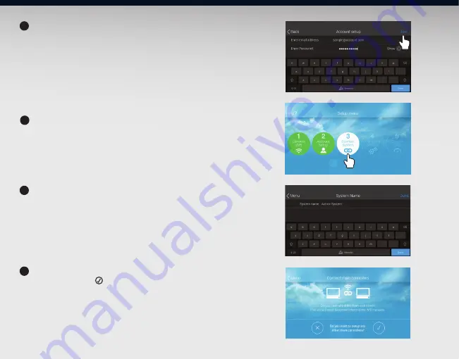
1

2

3

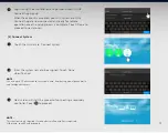
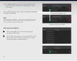
Next screen will start the process of connecting a secondary 
controller. Touch   to proceed.  

Enter the system name to be assigned. Touch ‘Done’ 
when finished.

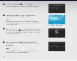
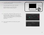
(3) Connect System 


Touch the third circle, ‘Connect System’.

Log-in using the email address and password used in QUE 
Connect App sign up. 

When the account is accepted, your A/C system and QUE 
Connect App are now connected and ready for remote 
operation once the setup process is complete. Touch ‘Done’ to 
proceed to next process.

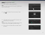
NOTE:


This section is only required if a secondary wall controller is required. 
Otherwise, touch X and proceed. 

NOTE:


Can use up to 30 characters for a system name. Avoid using non-alphanumeric 
and foreign characters.

Summary of Contents for QTB-1000

Page 1: ...Installation and Commissioning Manual ...

Page 2: ...2 Available in two colours Please read this manual carefully and keep it for future reference For more details contact ActronAir on 1800 119 229 QTW 1000 White QTB 1000 Black ...

Page 3: ...Sensor Installation 7 Start up 11 Connect WiFi 11 Account setup 12 Connect system 13 Setting up a non zoned system 15 Setting up a zoned system 16 Configure settings 22 System test 23 Installation details 27 Frequently Asked Questions 28 Specifications 30 ...

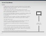
Page 4: ...s these locations may alter sensor readings Do not install the master controller near magnetic metallic objects or install near power cables as these may effect the wireless data signal it sends and receive Avoid looping excess cable Ensure there is ample space around the wall controller 100mm min to ensure proper air temperature reading and adequate access for service It is required to use the pr...

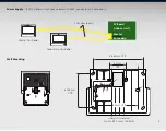
Page 5: ...E spec cables with RJ45 connectors cable boots 43mm CTR 84mm CTR Overall Dimension H x W 96 7mm x 132 5mm 61 44mm CTR 98 54mm CTR Master Controller Secondary Controller PC Board Indoor Unit 30m Max each Master Secondary Wall Mounting ...

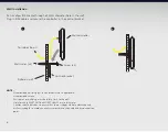
Page 6: ... lieu of wall mates if applicable Use provided screws Wall mates or wall plug must be totally flush to the wall Hole for cable MUST NOT be MORE THAN 25 mm in diameter Caution should be taken to ensure that there is adequate hole clearance and wall cavity depth to avoid unnecessary pressure to the cable and its connection point Control bracket Wall controller Plyboard wall Wall mates x2 Screw x2 a ...

Page 7: ...Avoid looping excess cable Ensure there is an ample space 100mm around the zone device to ensure proper air temperature reading and access for removal It is required to use the provided wall anchors and screws to secure the device on the wall If a zone device is required to be replaced remember to unpair the existing controller and pair the new one to the master controller Use a maximum of 20m RJ4...

Page 8: ...VDC power supply at the same time This type of set up will prevent the zone controller to show battery replacement reminder Please use good quality batteries when it comes time for replacement To damper motor Maximum 20m from the nearest power junction b AAA Battery Supply ii or via 8Z Module i Via damper motor option 8Z Module 1 5V AAA 1 5V AAA 1 5V AAA 1 5V AAA 1 5V AAA 1 5V AAA 1 5V AAA 1 5V AA...

Page 9: ...nt H x W 51 3mm x 63 3mm 43mm CTR Zone Device Combination Options Option Device s Temperature Averaging 1 Zone Controller 2 Remote Sensor 3 Zone Controller Remote Sensor 4 Remote Sensor Remote Sensor 5 Master Controller 6 Master Controller Remote Sensor 7 Master Controller Secondary Controller ...

Page 10: ...bracket Zone controller remote sensor Plyboard wall Wall mates x2 Screws x2 1 2 NOTE Use screws provided Use provided wall plug x2 in leu of wall mates if applicable Wall mates or wall plug must be totally flush to the wall Hole for cable MUST NOT be MORE THAN 25 mm in diameter Caution should be taken to ensure that there is adequate hole clearance and wall cavity depth to avoid unnecessary pressu...

Page 11: ...your access point from the WiFi network list 4 Enter the WiFi password then touch Join 5 When the WiFi is successfully connected touch Next to proceed to next process Account Setup NOTE QUE System must have a user account and internet connection in order to use features such as energy history remote connection via QUE Connect App and over the air OTA software updates QUE system connection to inter...

Page 12: ...om App Store iOS or Google Play Android for corresponding smart devices Open the app then touch sign up Use a valid email address and unique password Follow the on screen instructions to finalise your account set up NOTE This process will be skipped if internet connection is not available This may be completed later by going to Menu then select Settings then Account Settings Download and usage of ...

Page 13: ...ess and password used in QUE Connect App sign up When the account is accepted your A C system and QUE Connect App are now connected and ready for remote operation once the setup process is complete Touch Done to proceed to next process NOTE This section is only required if a secondary wall controller is required Otherwise touch X and proceed NOTE Can use up to 30 characters for a system name Avoid...

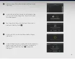
Page 14: ... SSID point as the master controller When successful the screen will show that 1 main controller has been connected Touch to proceed Check the serial number to ensure that the correct controller is connected Touch Done to proceed to next process Next screen will show the two controllers connected WiFi strength and serial numbers of both controllers are displayed on the screen NOTE Once connected t...

Page 15: ... on screen instructions It is possible to use the secondary controller if connected This will be visible on screen The next process will begin the setup of your system and or connecting zone devices Touch system or zone set up is required in the system otherwise touch NOTE Touching will use the default configuration As a default sensor assigned is from master wall controller Proceed to 4 Account S...

Page 16: ...sor record the serial number shown on the back of the device and ensure that the same number appears on the master controller screen during the setup Assigned to remote sensor Assigned to master controller b a Setting up a Zoned System After step 8 on page 15 to setup touch any zones connected to the system Touch Zone name to assign a name Then touch Add a zone device to add a device For each zone...

Page 17: ...o connect to the main controller This device is now connected to the main controller Please return to the main to complete setup controller Please wait VX XX Option 1 Zone will use the zone controller i Touch A new zone controller ii Follow the on screen instructions iii On the right side of the zone controller press and hold the pair button for three seconds Green blinking light means pairing is ...

Page 18: ...ler is now paired to the zone It will also show the serial number of the connected device Make sure this is the same serial number of the actual connected device check the back of the device for serial number Touch Back Option 2 Zone will use a remote sensor i Touch A new remote Sensor ii Follow the on screen instructions ...

Page 19: ... the Remote Sensor is now paired to the zone It will also show the serial number of the connected device Make sure this is the same serial number of the actual connected device check the back of the device for serial number Touch Back Green blinking light means pairing is successful Red blinking light means pairing has failed Repeat this step until pairing is successful Pair button press here ...

Page 20: ...the same process as using zone controller in Option 2 iii Setup screen will show two devices are paired to the zone NOTE It is also possible to pair the zone controller first before pairing the remote sensor Option 4 Zone is assigned to two remote sensors Follow the same process as Option 4 However instead of zone controller select zone sensor as a second device NOTE Pairing two zone controllers i...

Page 21: ...e Master Controller is now paired to the zone Touch Back iv Zone summary will also show Master Controller is paired to the zone NOTE If there is a secondary controller used on the system it is possible to use it instead of master controller NOTE It is possible to add a second zone device to average temperature reading This maybe a remote sensor or secondary controller if available ...

Page 22: ...djust the date and time slide the Auto set switch to the left Then follow steps 3 5 Touch Date and time to show adjustment dial Scroll through the day month year hour and minute dial to set the correct date and time Touch to accept the new setting Touch Time zone to select the city on the list of option shown Touch Done to exit To set time format slide the switch to the left for 12hr format Leave ...

Page 23: ...en finished display will show the number of zones connected to the system a Shows test result for zoned system b Shows test result for non zoned system 1 2 3 4 5 NOTE Ensure that the number of zones connected to the system is shown on the zone detection test summary If not check for any loose connections or defective zone motors then run zone detection test again ...

Page 24: ...there is air coming out If yes touch and proceed to step 9 Otherwise touch then check the indoor fan is wired correctly Repeat step 6 8 to run fan test again 1 System will now start to initiate indoor self learn test for zoned system This process step 9 11 will be skipped if the system is non zoned 6 7 8 9 ...

Page 25: ...ion appears 1 Next step will start Run system to check if the system is cooling and heating Touch Start Cancel 1 System will start 3 minutes countdown before it begins cooling test 1 Screen will show the system in cooling Wait for the compressor speed to reach more than 50 Go to nearest air outlet and observe if the air is cold If yes touch Start Cancel to proceed to heating test 10 11 12 13 14 ...

Page 26: ...h more than 50 Go to nearest air outlet and observe if the air is warm If yes touch Start Cancel Finish to end the heating test 1 When the system test is successful all test points will be ticked Touch Done to exit After all system test are completed touch Finish Setup 1 System setup is completed Display will show master controller main screen 15 16 17 18 ...

Page 27: ...t servicing contact details Complete the information below for future reference Zoned System Yes No System Name Controller Serial Number Master Wall Controller Secondary Wall Controller if applicable Zone Number Zone Name Zone Device Serial Number Zone 1 Zone 2 Zone 3 Zone 4 Zone 5 Zone 6 Zone 7 Zone 8 NOTES 27 ...

Page 28: ...e Master Controller to be in range what options are available A We recommend that you investigate if the Master Controller can be relocated to a more suitable location within the specified range Alternatively you can consider installing a secondary Master Controller which acts as a RF repeater which increases signal coverage 4 Q Can I use a WiFi booster to improve the range of the Master and Secon...

Page 29: ...I replace a defective Master Controller do I need to set up the whole system again A Yes You need to complete the commissioning process again 9 Q If I replace a defective Secondary Controller do I need to set up the whole system again A No Simply connect the new Secondary Controller ensuring it is configured to the same WiFi connection as the Master Controller Then from the Master Controller simpl...

Page 30: ...ield direct line of sight RF range 30m max in open field direct line of sight Sensors Temperature Sensor 0 5o C accuracy Humidity Sensor 5 accuracy Proximity Light Sensor 10 cm range detection Speaker Touch Screen Sound Yes Environmental and Standards Operating temperature 0o C to 50o C Storage temperature 20o C to 55o C Humidity 5 to 95 non condensing Mechanical Dimensions mm 154 x 122 x 22 W x H...

Page 31: ...31 Notes ...

Page 32: ...Copyright 2017 All rights reserve No part or contents of this book maybe reproduced or transmitted in any form or by any means without the written permission of Actron Engineering Pty Ltd 9590 6001 v8 ...

Reviews: