background image

7

ActronAir 

®

 is constantly seeking ways to improve the design of it’s products, therefore specifications are subject to change without notice. Please check prior to purchase.

Copyright © 2016 Actron Engineering Pty. Ltd.

CONTROL INTERFACE FUNCTIONS

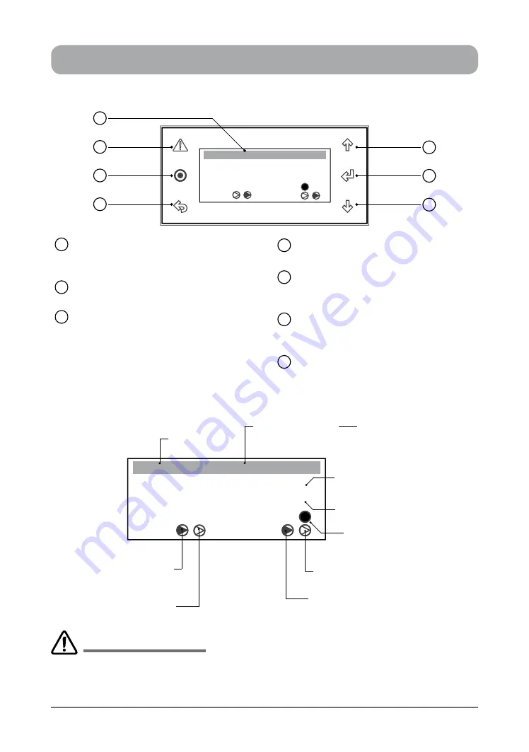
CONTROL INTERFACE FRONT VIEW

LCD Display

Displays the setting and operation 

conditions (see menu page for details).

Alarm / Reset  Button

Alarm Indication and Reset Button.

Program Button

To bring-up programming Main Menu 

screen. (Display will revert back to 

default screen after 5 minutes idle time 

at any stage of programming). 

1

2

3

ESC Button

To exit programming menu.

Scroll Up / Increment Button

To scroll up from existing menu or to 

increase setting parameter.

Enter Button

To lock the selected menu or to enter 

set parameters.

Scroll Down / Decrement Button

To scroll down from existing menu or to 

decrease setting parameter.

4

5

6

7

SYSTEM DEFAULT SCREEN


Room T. :

23.7

o

C


o

C


Supply T. :


Comp


Rev Vlv


Defrost


10:20            Unit: Unit ON

3

4

2

1

6

5

7


Room T. :

23.7

o

C


o

C


Supply T. :


Comp


Rev Vlv


Defrost


10:20            Unit: OFF by KEY

Current Time

Unit Control Indicator

 by Control Interface

Actual Room Air 

Temperature

Reversing Valve 2

ON / OFF Indicator

Actual Supply Air Temperature

 (Not Available)

Defrost Cycle 

Indicator

Reversing Valve 1

ON / OFF Indicator

(Dark Filled arrow indicates ON)

Compressor 2

ON / OFF Indicator

(Dark Filled arrow indicates ON)

Compressor 1

ON / OFF Indicator

Other Unit Control Indicators:  

• by Timeclock

• by 3rd Party

• by DRM

• by BMS

CP05 

and 

CP10

 are two identical control interfaces with the same display and functions. The only differences 

are the interface buttons and front case appearances. 

CP05 is supplied as standard, 

while 

CP10

 is supplied 

as optional control interface for commercial range air conditioning systems. This manual covers operations 

applicable to both control interfaces, however CP05 control interface features are shown for ease of illustrations.

IMPORTANT NOTES

Summary of Contents for CP05

Page 1: ...e unit for future reference Copyright 2016 Actron Engineering Pty Ltd All rights reserved This manual is a controlled document which contains confidential and proprietary information Distribution modification copying and or reproduction are prohibited without written consent from ActronAir COMMERCIAL AIR CONDITIONING SYSTEM CONTROL INTERFACE Operating Instructions Model Number CP05 Supplied as Sta...

Page 2: ...erface Functions 7 Initialisation Displays Status Indications 8 Defrost Operation Indications 9 Menu Tree Diagram Consumer End User Menu 10 Sub Menu Level Descriptions 11 Turn Unit ON OFF via Control Interface 12 Backlight 13 Setting Room Temperature Setpoint 14 Setting the Temperature Setback 15 Operation Mode 16 Setting the Clock 18 Day Light Saving Time Enable 20 Day Light Saving Time Disable 2...

Page 3: ...reach the expected results in relation to the specific design and system installation ActronAir based on specific agreements may be consulted for the positive commissioning installation and application of the unit however in no case does ActronAir accept liability for the correct operation of the final equipment system Your ActronAir air conditioning unit is one of the most advanced innovative pro...

Page 4: ...o improve the design of its products therefore specifications are subject to change without prior notice Please check with your ActronAir Technical Support Department on toll free number 1800 119 229 Storage Operating Conditions Storage conditions 20 to 70 o C 90 RH non condensing Operating conditions 10 to 60 o C 90 RH non condensing Waste Electrical Electronic Equipment Disposal Guidelines 1 Do ...

Page 5: ...or servicing must be carried out by a qualified installer or technician 8 Ensure that the unit installation complies with relevant council regulations and building code standards All electrical wiring must be in accordance with current electrical authority regulations and all wiring connections to be as per electrical diagram provided 9 WH S rules and regulations must be observed and will take pre...

Page 6: ...nditioner The controller will detect this frost build up and will automatically activate the defrost mode 6 Hot Start Function Heating Mode When the air conditioner starts in heating mode the indoor fan is delayed for a short period of time this allows the heat exchanger to warm up before the air flow starts thus preventing cold drafts The hot start feature also activates itself when the system fi...

Page 7: ...eter 4 5 6 7 SYSTEM DEFAULT SCREEN Room T 23 7 o C o C Supply T Comp Rev Vlv Defrost 10 20 Unit Unit ON 3 4 2 1 6 5 7 Room T 23 7 o C o C Supply T Comp Rev Vlv Defrost 10 20 Unit OFF by KEY Current Time Unit Control Indicator by Control Interface Actual Room Air Temperature Reversing Valve 2 ON OFF Indicator Actual Supply Air Temperature Not Available Defrost Cycle Indicator Reversing Valve 1 ON O...

Page 8: ...logo will then be displayed for the next 5 10 seconds Compressor 1 Reversing Valve 1 are On System in Heat Mode first triangles are darkened Room T 23 7 o C o C Supply T Comp Rev Vlv Defrost 10 20 Unit Unit ON Room T 23 7 o C o C Supply T Comp Rev Vlv 10 20 Unit Unit ON System Screen default provides an overview of system status showing the Room Temperature Supply Temperature Compressors Reversing...

Page 9: ...3 7 o C o C Supply T Comp Rev Vlv 10 22 Unit Unit ON Defrost Room T 23 7 o C o C Supply T Comp Rev Vlv 10 23 Unit Unit ON Room T 23 7 o C o C Supply T Comp Rev Vlv 10 23 Unit Unit ON Room T 23 7 o C o C Supply T Comp Rev Vlv 10 23 Unit Unit ON Room T 23 7 o C o C Supply T Comp Rev Vlv 10 26 Unit Unit ON Call for Defrost System 2 Comp 2 Off Comp 2 and Rev Valve 2 Off Comp 2 and Rev Valve 2 Off Comp...

Page 10: ...m Log Log 2 Recent Alarm UP TO Supply Fan Speed Status Condenser Fan Speed Status Economy Cycle Output Status Boost Heater Output Feature N A Refrigeration Circuit Crt 1 2 or 3 Compressor Status Reversing Valve Status Cond Fan Low Speed Status Cond Fan Hi Speed Status E Status Discharge Temp Crt 1 2 or 3 Outdoor Coil Temp Crt 1 2 or 3 Room Temp Outside Air Temp External Indoor Fan Speed Status Ext...

Page 11: ... Level 4 Menu screen to set the date time E Status Sub Menu Level 5 Read only Menu screen to view the unit running conditions such as Room Air temperature Fan Speed Outside temperature LP HP Discharge Temperature OD Fan Speed etc F Alarm History Sub Menu Level Read only Menu screen that indicates the alarm history A On Off Unit B Setpoint Main Menu 1 8 C Mode of Operation NOTE Only up to level 6 c...

Page 12: ...URN OFF THE UNIT SELECT FAN ONLY MODE 6 Repeat Steps 1 2 then press Button cursor will appear and start blinking near ON 7 Press or Button to select switch OFF or FAN ONLY position Display will show the On Off Unit page with switch symbol pointing towards OFF or FAN ONLY and the cursor will still be blinking 8 Press Button to Turn Off the unit or switch to the FAN ONLY mode The cursor will disappe...

Page 13: ...ock in the selected display backlight setting and the cursor will disappear The backlight will imediately Turn ON OFF depending on the selected mode NOTES On AUTO mode the Backlight will Turn Off in 5 minutes after the last button is pressed Backlight will instantly Turn ON OFF when either of the mode is selected TO RETURN TO THE MAIN MENU 7 Press Escape Return Button twice to return to the Main M...

Page 14: ...int temperature The cursor will disappear and the new room setpoint temperature will be displayed TO RETURN TO THE MAIN MENU 7 Keep pressing Escape Return Button until you get to the Main Menu screen Otherwise press Button Display Progression A On Off Unit B Setpoint Main Menu 1 8 C Mode of Operation A On Off Unit B Setpoint Main Menu 2 8 C Mode of Operation Setpoint 23 0o c Temperature setback DI...

Page 15: ...ps 6 7 above to set the heating temperature setback NOTE Heating temperature setback can be selected between 10o C to 20o C TO RETURN TO THE MAIN MENU 9 Keep pressing Escape Return Button until you get to the Main Menu screen Otherwise press Button Display Progression A On Off Unit B Setpoint Main Menu 1 8 C Mode of Operation A On Off Unit B Setpoint Main Menu 2 8 C Mode of Operation Setpoint 22 0...

Page 16: ...ve to the next menu item indicating that the operation is now in COOL ONLY mode NOTES Mode of Operation menu will be locked for 3 min after changing mode as a safety time delay in order to prevent frequent mode changes To select HEAT ONLY or AUTO CHANGE OVER mode follow steps 4 to 6 above CHANGING THE FAN MODE 7 Follow steps 1 to 4 above and then press Button to get into the Fan mode selection men...

Page 17: ...mode Continuous Operation Mode Mode COOL ONLY Fan mode Continuous Step 4 Step 5 Step 6 Operation Mode Mode COOL ONLY Fan mode Continuous Operation Mode Mode COOL ONLY Fan mode Auto Cycle Operation Mode Mode COOL ONLY Fan mode Continuous Operation Mode Mode COOL ONLY Fan mode Auto Cycle Step 7 Step 8 Step 9 Operation Mode Mode COOL ONLY Fan Speed LOW Fan mode Continuous Operation Mode Mode COOL ONL...

Page 18: ...ess Button to lock in the Month and the cursor will move next to the year date 9 Press or Button to change the year NOTE Day changes corresponding to the change in year as follows Sunday 22 09 13 22nd September 2013 Tuesday 22 09 15 22nd September 2015 SETTING THE CLOCK Display Progression A On Off Unit B Setpoint Main Menu 1 8 C Mode of Operation C Mode of Operation B Setpoint Main Menu 4 8 D Clo...

Page 19: ...ion B Setpoint Main Menu 4 8 D Clock Scheduler Step 13 12 56 Step 13 12 58 Step 14 Step 15 A On Off Unit B Setpoint Main Menu 1 8 C Mode of Operation Step 15 10 Press Button to lock in the Year Date and the cursor will move next to the hour indicator 11 Press or Button to change the hour NOTE The Hour display is in 24 hour format This can be changed with an incremental value of 1 hour 12 Press But...

Page 20: ...d in at 00 Step 7 Step 8 Step 9 January Step 9 October 1 From the main menu scroll down to D Clock Scheduler menu following the procedures from Setting the Clock section 2 Press Button to enter D Clock Scheduler main menu 3 Press Button to scroll down to Daylight Saving Time sub menu 4 Press Button to enter Daylight Saving Time sub menu and the cursor will appear on ENABLE indicator If the indicat...

Page 21: ...in Menu 1 8 C Mode of Operation Step 15 10 Press or Button to select the Day for transition into daylight saving time e g SUNDAY 11 Press Button to lock in Sunday for the transition to occur i e FIRST SUNDAY The cursor will next move to the starting month selection segment 12 Press or Button to select the Month for transition into daylight saving time 13 Press Button to lock in the Month for trans...

Page 22: ...croll down to D Clock Scheduler menu following the procedures from Setting the Clock section 2 Press Button to enter D Clock Scheduler main menu 3 Press Button to scroll down into Daylight Saving Time sub menu 4 Press Button to enter Daylight Saving Time sub menu and the cursor will appear on ENABLE indicator 5 Press or Button to select the DISABLE Daylight Saving Time function NOTE The segment wi...

Page 23: ...ler Yes Date 22 09 14 Day Monday Clock Display Progression C Mode of Operation B Setpoint Main Menu 4 8 D Clock Scheduler Hour 10 28 Enable Scheduler No Date 22 09 14 Day Monday Clock Hour 10 28 Enable Scheduler No Date 22 09 14 Day Monday Clock Hour 10 28 Enable Scheduler Yes Date 22 09 14 Day Monday Clock Step 1 Step 2 Step 3 Step 4 Hour 12 58 Enable Scheduler Yes Date 22 09 14 Day Thursday Cloc...

Page 24: ...and the cursor will next move to Monday Event 2 starting hour indicator Example Monday ending time is set to 9 30 AM i e 09 30 13 Repeat steps 7 11 to set up Monday Event 2 starting ending time and the cursor will next move to Tuesday Event 1 starting hour indicator Example Monday Event 2 starting ending times are at 17 30 and 22 00 respectively 14 Repeat steps 7 12 to set up the succeeding days p...

Page 25: ...eration duration 2 0 H set to 0 to disable Clock Schedule 05 After Hours operation duration 1 0 H set to 0 to disable Clock Schedule 05 Step 4 Step 5 Step 6 C Mode of Operation B Setpoint Main Menu 4 8 D Clock Scheduler A On Off Unit B Setpoint Main Menu 1 8 C Mode of Operation Step 7 1 From the main menu scroll down to D Clock Scheduler menu following the procedures from Setting the Clock section...

Page 26: ...in setting up Events 1 2 from 7 Day Programming section and the cursor will move to the next Clock Schedule sub menu 10 Repeat steps 4 8 above to set up the succeeding special days programming start and end times NOTES The scheduled program events for each nominated special day will be in operation everytime each nominated day and events occurs during the year i e the program events for Special Da...

Page 27: ...ck Schedule 06 Step 3 Step 4 Step 5 Day 6 Special Day 1 Month Jan Event 1 00 00 to 00 00 Event 2 00 00 to 00 00 Clock Schedule 06 Day 6 Special Day 1 Month Dec Event 1 00 00 to 00 00 Event 2 00 00 to 00 00 Clock Schedule 06 Day 6 Special Day 1 Month Jan Event 1 00 00 to 00 00 Event 2 00 00 to 00 00 Clock Schedule 06 Day 6 Special Day 1 Month Jan Event 1 06 00 to 10 00 Event 2 15 00 to 21 00 Clock ...

Page 28: ...1 Fan 20 0 Condenser 2 Fan 20 0 Input Output 07 C Mode of Operation Main Menu 5 8 D Clock E Status Step 5 Step 6 Step 7 A On Off Unit B Setpoint Main Menu 1 8 C Mode of Operation Step 7 1 Press Button to get into the Main Menu Display will show Main Menu and highlighted Sub Menu A On Off Unit 2 Press Button to scroll down to E Status sub menu 3 Press Button to enter E Status sub menu Display will ...

Page 29: ...be cleared but remain in the alarm history See Warning Note below TO CLEAR THE ALARM HISTORY 8 From the F Alarm History menu press Button two times to get into Reset alarm log screen Press the Button if you are in any of the alarm log 9 Press the Button The cursor will appear on the No option 10 Press or Button to change the prompt to Yes and then press the Button again to clear the Alarm History ...

Page 30: ...Temp 0 0 o C Alarm History AL29 No 016 15 52 22 09 14 Room Temp 18 3 o C Comp 2 HP Supply Temp 0 0 o C Alarm History AL30 No 018 16 02 22 09 14 Room Temp 18 3 o C Comp 1 HP Supply Temp 0 0 o C Alarm History AL28 No 015 15 32 22 09 14 Press 2 Times Step 5 Step 6 Step 7 F Alarm History Main Menu 6 8 D Clock E Status Room Temp 18 3 o C Comp 1 LP Supply Temp 0 0 o C Alarm History AL29 No 016 15 52 22 ...

Page 31: ... Fault Warning Temperature out of Range Temperature OK Outdoor Coil Temp2 Fault Warning Temperature out of Range Temperature OK Room Air Temperature Sensor Fault Warning Temperature out of Range Temperature OK Outside Air Temperature Sensor Fault Warning Temperature out of Range Temperature OK Filter Alarm Alarm Air Filter Timer Timed Out Clean Replace Filter and Reset Timer Anti Freeze Protection...

Page 32: ...itions Water from the outdoor unit This is normal during heating operation which is due to water forming on the heat exchanger Occurring of noises When heating or cooling is started or stopped a swishing or gurgling noise may be heared This noise is generated by the refrigerant flowing between the outdoor and the indoor units A swooshing noise may be heared from the outdoor unit during operation T...

Page 33: ...arm is indicated on the control interface Cleaning the Condenser Coils Clean the coils at least once a year or more frequently if unit is located in a dusty and or dirty environment in order to maintain your system s proper operating performance High discharge pressures are a good indication that the coils need cleaning When using detergent or solvents to clean the coils follow the manufacturer s ...

Page 34: ... Address SITE ADDRESS Date MODE OF OPERATION INDOOR FAN SETTINGS Mode ID Fan Speed Indoor Fan Mode Indoor Fan Airflow l s Return Air Temperature Setpoint o C Static Pressure kPa Temp Setback o C Indoor Fan Amps Amp Enable Scheduler Daylight Saving Time Set Transition Time min Start in at End in at Auto Cool Only Heat Only Continuous Auto Cycle Enabled Disabled Yes No Yes No TIMECLOCK SETTINGS Even...

Page 35: ...ool Proportion band o C 4 Heat Proportion band o C Supply Air Temp NTC 5 Integral Time seconds Phase Fail Relay 6 Room temp probe weight value 0 10VDC In Fan Spd 0 10VDC 7 Supply Fan Min Speed 0 10VDC Stage Cont 0 10VDC 8 Supply Fan Med Speed Night Mode Enable 9 Supply Fan Max Speed Economy Enable 10 Supply Fan Min Temp o C 11 Supply Fan Max Temp o C Multi Input 2 12 Supply Fan Continuous 13 Cycle...

Page 36: ... Ltd ABN 34 002 767 240 HEAD OFFICE SYDNEY AUSTRALIA Copyright 2016 Actron Engineering Pty Ltd Printed in Australia Part No 0525 031 Ver 3 190308 1800 119 229 www actronair com au Refrigerant Trading Authorisation No AU06394 ...

Reviews: