ACS A1270 EMAT Operation Manual Download Page 24

А1270 Electro-Magnetic Ultrasonic Thickness Gauge

Operation Manual

24

ACOUSTIC 

CONTROL 

SYSTEMS

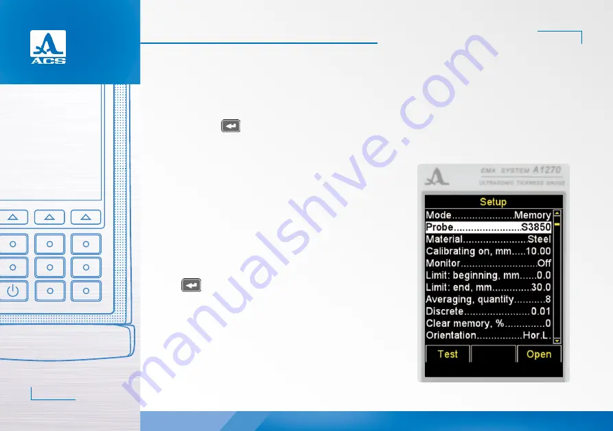
2.3.2.2 Probe option

- Enters the library with transducers.
Active keys:
F1 (Test): starts the testing procedure of EMAT adjustment of the instrument to the selected transducer;
F3 (Open) or 

: enters the library with transducers.

The Probe option is shown on the screen, Figure 20. 
- Viewing the library with transducers.
The window header will show information on the currently used EMAT 

“Current probe:”.

ATTENTION:

 USERS MAY NOT ADD THE TRANSDUCERS (PROBES) TO THE 

LIBRARY AND EDIT THE LIBRARY INDEPENDENTLY!

Active keys:
F1 (Test): starts the procedure of adjustment of the EMAT individual pa-

rameters.

F2 (View): provides viewing of the detailed information on a transducer. 

The name, type and frequency of the EMAT is displayed on the screen.

F3 (Exit): returns to the main window of the SETUP mode.

  selects the transducer from the list. The testing procedure of 

EMAT adjustment to the parameters of the instrument will be started auto-
matically. The detailed description of the procedure is given in the paragraph 
2.2.3.2.

Upon exiting the library, the instrument will remember the last active line 

and will set it upon the next library entry. Upon switching Off the instrument 
information on the active line of the library will be set to zero.

Figure 21: the screen of the instrument when viewing the library with 

transducers.

Figure 20

2

Summary of Contents for A1270 EMAT

Page 1: ...hickness Gauge Operation Manual 1 ACOUSTIC CONTROL SYSTEMS ELECTRO MAGNETIC ACOUSTIC THICKNESS GAUGE WITH THE NOVEL ELECTRO MAGNETIC BIASING TECHNOLOGY Acoustic Control Systems Solutions GmbH Saarbr c...

Page 2: ...1270 Electro Magnetic Ultrasonic Thickness Gauge Operation Manual 2 ACOUSTIC CONTROL SYSTEMS...

Page 3: ...NS 7 1 3 DESIGN AND OPERATION 8 1 3 1 Design 8 1 3 2 Operation principle 10 1 3 3 Operation modes 10 1 3 4 Display 11 1 3 5 Keypad 15 2 PROPER USE 16 2 1 OPERATING RESTRICTIONS 16 2 2 MAKING THE INSTR...

Page 4: ...The MEMORY mode 44 2 3 4 The B SCAN mode 47 2 3 5 The SCAN mode 49 2 4 DOING MEASUREMENTS 52 2 4 1 Functional check out of the instrument during inspection 52 2 5 DATA TRANSFER TO PC 53 3 TECHNICAL MA...

Page 5: ...a corresponding training and having read the operation documentation is al lowed to work with the instrument To perform the correct ultrasonic inspection the inspection tasks must be determined the in...

Page 6: ...in various industries The A SCAN mode allows the elimination of false readings thus substantially increasing inspection reliability ex press searches for foreign inclusions and laminations as well as...

Page 7: ...H 0 1 Indication discreteness of thickness mm for thickness values up to 99 99 mm for thickness values from 100 0 mm 0 01 0 1 0 1 Setting range of the ultrasonic sound velocity m s from 1 000 to 9 99...

Page 8: ...l are shown on the display The display is used for a vi sual monitoring of the measurement process via the color coded indication A membrane keypad under the display allows to use the instrument funct...

Page 9: ...ower adapter to charge the built in battery Figure 3 Note During the charging no measurements are possible The Micro B connector of the USB cable shall be connected by the symbol and or the B letter f...

Page 10: ...on modes of the thickness gauge are as follows MEMORY is the measurement mode with the indication of the recorded results B SCAN is the measurement mode with the graphical indication of the profile te...

Page 11: ...parameters specific for each measurement mode 1 3 4 Display In all operation modes the upper line on the display indicates the information on the current operation mode of the instrument and its batt...

Page 12: ...well Table 3 description of indicators of the ultrasonic contact and measurement method Indicator Description Maximum signal level the amplification of the receiving channel is set to the minimum val...

Page 13: ...tab of the MEMORY mode Accumulator charge level Measurement units Ultrasonic waves velocity in current material Field to record the measurement result Signal level indicator Input field for measuremen...

Page 14: ...r part of the screen The instrument allows to rotate the image by 90o to the right or to the left in the operation mode Depending on the selected image layout the display indication changes vertical h...

Page 15: ...S PRESSED AND NO MEASUREMENT IS PERFORMED The functional keys F perform various functions depending on the selected operation mode of the instru ment The name of the current function is displayed unde...

Page 16: ...noid are included in the basic delivery kit EMAT S7392 3 0A0D10ES and S7394 2 5A0R10x10ES with permanent solenoid can be connected to the electronic unit of the instrument using a special connector Th...

Page 17: ...STARTING THE OPERATION AND IF THE TRANSDUCER IS CHANGED CONFIGURE AND ADJUST THE INSTRUMENT TO THE INDI VIDUAL PARAMETERS OF THE USED EMAT Otherwise the instrument will not operate Any attempt to swit...

Page 18: ...e F1 key Test The screen will dis play the message PROBE ZEROING Take the probe and holding it in your hands press ENTER Not letting EMAT to contact the calibra tion sample press the key The message T...

Page 19: ...tive the instrument will switch into the measurement mode if the test result is negative the instrument will return to the main window of the SETUP mode At any step the testing procedure can be cancel...

Page 20: ...velocity calibration with the sample transfer of the data to PC viewing the library of the transducer and operation with the library of materials All settings of the instrument will be saved after it...

Page 21: ...locity calibration with the sample Averaging quantity 1 2 4 8 16 Increasing of average value improves the noise signal ratio by repeated summing of the signal in time Discrete 0 01 0 1 Setting the res...

Page 22: ...the upper response limit of the display Clear memory from 0 to 100 Indication of the volume of the used memory Starts the procedure of deletion of the measurement results from the memory Menu option...

Page 23: ...sponding parameters in the metric measurement system and functions are listed in the Table 7 2 3 2 1 The MODE option Select the measurement mode MEMORY the measurement results stored in the memory are...

Page 24: ...Test starts the procedure of adjustment of the EMAT individual pa rameters F2 View provides viewing of the detailed information on a transducer The name type and frequency of the EMAT is displayed on...

Page 25: ...3 2 3 MATERIAL option Enters the library with materials Active keys F2 Open or enters the library with materials to record new materials into the memory and edit the existing and to select the materi...

Page 26: ...de Active keys F1 exits the editor saving the changes F2 XXX switching between the characters in the letter table Russian small letters Russian capital letters abc English small letters ABC English ca...

Page 27: ...value will start decreasing or increasing depending on the key which was used Using the keys or set the required velocity value of the ultrasonic sound Press the key the velocity value will change its...

Page 28: ...ain window of the SETUP mode selects the material for operation and returns to the main window of the SETUP mode Upon exiting the library the instrument will remember the last active line and will set...

Page 29: ...e 27 Active keys F1 or decreases the thickness value of the calibration sample F2 Run starts the procedure of velocity calibration with the sample F2 or decreases the thickness value of the calibratio...

Page 30: ...procedure of velocity calibration with the sample The message Put the probe on calibrating sample and press ENTER is displayed on the screen Apply some coupling liquid on the sample Place EMAT on the...

Page 31: ...en The screen layouts orientation of the instrument during the calibration procedure are shown subsequently in the Figure 28 Saving the velocity value obtained during calibration Active keys F1 Yes sa...

Page 32: ...Active keys F1 min max range selection MIN MAX F3 0 max selection of the range 0 MAX 2 3 2 6 Monitor option only for the MEMORY mode Setting the actuation conditions for color sound and vi bro alarms...

Page 33: ...n the Figure 33 Active keys F1 or decreases the value of the lower actuation limit of the Monitor F2 or increases the value of the lower actuation limit of the Monitor 2 3 2 8 The LIMIT end only for t...

Page 34: ...keys F1 or decreases the averaging value F2 increases the averaging value 2 3 2 10 The DISCRETE option Setting the discreteness of the image indication on the screen The screen DISCRETE option for the...

Page 35: ...ge of the memory with the measurement results is specified as an option parameter The screen CLEAR MEMORY option is shown in the Figure 37 Active keys F2 Run or starts the procedure of memory cleaning...

Page 36: ...option is shown in the Figure 39 Active keys F1 or decreases the value of the scan beginning F2 or increases the value of the scan beginning 2 3 2 13 The SCAN END option only for the SCAN mode The opt...

Page 37: ...e Figure 41 Active keys F1 or decreases the value of the lower limit of the strobe gate F2 or increases the value of the lower limit of the strobe gate 2 3 2 15 The option Gate end only for the SCAN m...

Page 38: ...e Figure 43 Active keys F1 or decreases the gain value F2 or increases the gain value Figure 43 Figure 44 2 3 2 17 The A SCAN TYPE option only for the SCAN mode Selecting the type of the signal indica...

Page 39: ...D option Switching On Off the sound indication of the instrument For the convenient operation of the thickness gauge the main events of the thickness gauge during measurements adjustment and key press...

Page 40: ...lling to the right subsequent selection of the available interface languages Figure 47 Figure 48 2 3 2 20 The VIBRATION option Switching On Off the vibration indication For the convenient operation of...

Page 41: ...MM INCHES The screen MEASURING UNITS option is shown in the Figure 49 Active keys F1 mm the metric measurement units The thickness is displayed in mm the velocity is displayed in m s F3 inches the Bri...

Page 42: ...screen brightness F3 or increases the screen brightness 2 3 2 24 DATE option Setting the date The menu item DATE is shown in the Figure 51 Active keys F2 Edit start the date editing procedure The scre...

Page 43: ...Thickness Gauge Operation Manual 43 ACOUSTIC CONTROL SYSTEMS Figure 52 Figure 53 2 3 2 25 TIME option Setting the time The menu item TIME is shown in the Figure 53 The TIME editing procedure is simila...

Page 44: ...ted object The ultrasonic contact level indicator and the measurement method indicator will be displayed in the upper left corner If the acoustic indication is on in the menu of the Mon itor the chang...

Page 45: ...FROM THE INSPECTED OBJECT THE MEASUREMENT RESULT WILL IMMEDIATELY CHANGE TO THE HORIZONTAL STROKES saves the current result Note the result will be recorded into the first free cells of the last exist...

Page 46: ...The maximum quantity of the groups is 100 A corresponding explanatory text will be displayed by the instrument when the maximum quantity of the cells is reached in the group In practice recording the...

Page 47: ...nging the value recorded in the cell press the key Perform the measurement and press the key when the result is satisfactory to record it into the cell selected to be corrected Upon recording the inst...

Page 48: ...2 3 4 1 Viewing saved B Scans When the F1 Review key is pressed the view mode of the stored B Scans is started Active keys moving up and down in the column of the measurement results where the B Scan...

Page 49: ...rt the signal is shown as an Scan in the lower part the digital values of parameters and checking icons are shown Figure 59 Main active keys F1 monitoring the size and position of the strobe F2 monito...

Page 50: ...n Uponpressingthe keythemessageisdisplayedonthescreen Savecurrent Scan hereyoushallconfirm Figure 60 Note The result will be recorded in the first empty cell of the last existing group created in the...

Page 51: ...Scan saved for the selected result will be displayed in the upper part of the screen Figure 63 To return to the view mode of the results press the F2 Scan key The value recorded in the memory in the S...

Page 52: ...possibletoreceivemeasurementresultsfromacavityifthetransducercannotbeplacedonitsbottom TheEMATshallbeinstalledperpendiculartotheplaneoftheinspectedobject Don tforcetheEMATagainstthesurface WhentheEMAT...

Page 53: ...further viewing You can name the copied data file as you like The digital data shall be stored in the instrument in the CSV format which is convenient for export to various applications CSV means comm...

Page 54: ...in protection against overcharge over discharge over current and overheating The battery service life is designed for the whole guaranteed service life of the instrument The battery must be replaced b...

Page 55: ...by the personnel and unrestricted access to them The distance between the instruments and the walls floor of the warehouse and other warehoused instruments shall be at least 100 mm The distance betwe...

Page 56: ...instruments will be transported in an open transport vehicle The packaged instruments should be properly and steadily fixed to prevent shocks of devices against each and against vehicle walls during t...

Page 57: ...1270 Electro Magnetic Ultrasonic Thickness Gauge Operation Manual 57 ACOUSTIC CONTROL SYSTEMS NOTES...

Page 58: ...1270 Electro Magnetic Ultrasonic Thickness Gauge Operation Manual 58 ACOUSTIC CONTROL SYSTEMS NOTES...

Page 59: ...1270 Electro Magnetic Ultrasonic Thickness Gauge Operation Manual 59 ACOUSTIC CONTROL SYSTEMS...

Page 60: ...tic Ultrasonic Thickness Gauge Operation Manual 60 ACOUSTIC CONTROL SYSTEMS OPERATION MANUAL Revision February 2018 ELECTRO MAGNETIC ACOUSTIC THICKNESS GAUGE WITH THE NOVEL ELECTRO MAGNETIC BIASING TE...

Reviews: