background image

25

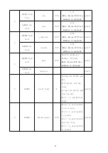
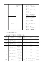
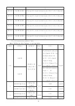
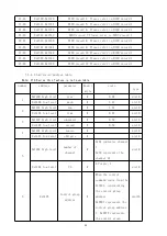
13-36

0x000C-23

Channel 1-24 state

R/W

0 points, 1 close,

0xFFFF means that the

loop is not available

0xEEEE indicates the

loop fault

uint16

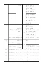
37-60

0x0024-3B

Channel 1-24

current current

R

Accurate to 2 decimal

places, in unit A

Note: Series 210 this

address is reserved

uint16

61-84

0x003C-53

Channel 1-24

current harmonic

content

R

At 1 decimal place, in

unit of%

uint16

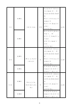
85-108

0x0054-6B

Channel 1-24

active power

R

3 decimal places in kW

uint16

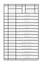
109-156

0x006C-9B

Channel 1-24

active electric

energy

R

3 decimal places in kWh

uint32

157-204

0x009C-CB

Channel 1-24 Relay

closing time

R

second

uint32

205-288

0x00CC-E3

Channel 1-24 relay

closing times

R

Times

uint16

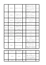
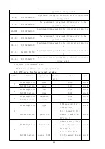
229-231

0x00E4-E6

A, B, C phase

voltage

R

At 1 decimal place, in

unit V

Note: Series 210 this

address is reserved

uint16

232

0x00E7

Voltage frequency

R

In 2 decimal places, in

the unit of Hz

Note: Series 210 this

address is reserved

uint16

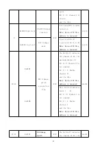
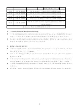
7.3.2 Parameter setting address table

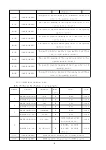
number

address

parameter

Read /

write

scale

type

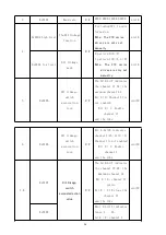
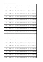
1

0x0101

address

R/W

1-247

Note: The 210 series

drives only manually

set the address 1-63

uint8

2

0x0102

obligate

Summary of Contents for ASL2 Series

Page 1: ...542 ASL2XX Series switch drives Installation of IFU V1 2 Jiangsu Acrel Electric MFG Co Ltd ...

Page 2: ...pied or disseminated in any form otherwise all consequences shall be borne by the violators The Company reserves all legal rights The Company reserves the right to modifications to the product specifications described in this manual without notice Before ordering please consult the local agent for the new specifications of this product ...

Page 3: ...uery 11 5 3 3 Time setting 12 5 3 4 Timing schedule setting 12 5 3 5 Timed plan view 13 5 3 6 DI DO linkage 15 5 3 7 RS485 communication settings 16 5 3 8 Other Parameters and information 17 6 Functional application 20 6 1 The heartbeat message 20 6 2 General functions 20 6 3 Scene function 20 6 4 Time function 20 7 The Newsletter Guide 20 7 1 Interface Overview 20 7 1 1 Transmission mode 20 7 1 2...

Page 4: ...7 3 3 Timing address table 28 7 3 4 Event record address table 33 8 Analysis and troubleshooting of common faults 36 9 Notes 36 ...

Page 5: ...220Z Sx 16 RS485 communication fire control linkage 2DI 2 DO 30 scheduled tasks including astronomical clock 24 scheduled tasks LCD display 600 switch records 10 switch records 12 DIDO records split and closed channels over zero trigger closing times record closing time accumulation voltage current measurement electric energy statistics ASL220 Sx 16 RS485 communication fire control linkage 2DI 2 D...

Page 6: ...A No active often open contact contact capacity AC 220V 1A DC 30V 1A communication ALIBUS Agreement and the Modbus RTU protocol way to install 35mm guide rail type installation service environment Operating temperature 10 55 Relative humidity 95 uncovered Storage temperature range 20 70 Local operation interface Key LCD monochrome LCD display Key dial code switch certainty of measurement Voltage c...

Page 7: ...ule width B modulus ASL220Z S4 16 4 144mm 8 Mod ASL220Z S8 16 8 216mm 12 Mod ASL220Z S12 16 12 288mm 16 Mod ASL220Z S16 16 16 360mm 20 Module ASL220Z S20 16 20 432mm 24 Mod ASL220Z S24 16 24 504mm 28 Mod Installation tip This module is suitable for 35mm guide rail installation installation only need to put the module into the track ASL210 Sx 16 Switch drive B ...

Page 8: ...dule ASL210 S12 16 12 252mm 14 Mod ASL210 S16 16 16 324mm 18 Mod ASL210 S20 16 20 396mm 22 Mod ASL210 S24 16 24 468mm 26 Mod Installation tip This module is suitable for 35mm guide rail installation installation only need to put the module into the track 4 2 Electrical wiring diagram ASL220Z Sx 16 Switch Drive same as ASL220 Sx 16 switch drive ...

Page 9: ...cuit switch control port 2 Relay manual operation hole Note The number of the switch loop is sorted from left to right 3 Programming buttons 4 working station indicator 5 Power supply input terminal 6 Display screen operation communication indicator DI DO indicator 7 Operation keys MENU menu key left key right key return and turn page 8 ALIBUS Communication interface 9 485 Communication and DI DO ...

Page 10: ...igure 4 shows the wiring diagram of the 4 way switch driver In practical use the 4 8 12 16 20 24 switch driver wiring is similar and they are not listed here 1 Lighting circuit switch control port 2 Relay manual operation hole Note The number of the switch loop is sorted from left to right 3 Programming buttons ...

Page 11: ...ines Figure 5 panel schematic diagram 5 1 Definlight definition 5 1 1 Light light of main module 1 A SL220Z Sx 16 Main Module indicator lamp the same as ASL220 Sx 16 Operating indicator light green Fllink about once per second when the module is in normally Communication indicator light green Blink flash once during module ALIBUS communication Long light bus congestion DI red Long light DI signal ...

Page 12: ... Description of the main module keys 1 A SL220Z Sx 16 main module button same as ASL220 Sx 16 ASL220Z Sx 16 main module has MENU menu key left key right key return key and page turning five keys The module can be modified to address and set parameters by pressing the button MENU menu key In the non programming mode press this key to enter the programming mode prompt for the password or return to t...

Page 13: ...etails see 5 3 6 DI DO linkage for ASL220 Sx 16 7 8 Dial up code invalid function reserved 9 Code linkage mode selection mode 0 means that when the DI signal input is detected the channel moves according to the preset action value Mode 1 represents that the channel moves according to the preset action value when the DI signal input is detected when the DI signal withdrawal is detected the channel ...

Page 14: ...e comes with liquid crystal display with switch drive status query information query time and timing plan query and setting DI DO linkage query and setting RS485 communication function query and setting other parameters query and setting 5 3 1 Switch drive status query 1 Power on shutdown and self test At the moment of power up the switch drive interface is shown in the following figure all indica...

Page 15: ...ress the MENU menu key to exit Note Channel 00 means all channels channel 01 represents the first channel and so on 5 3 2 Information query Under the status display interface press the page turning key to enter the information query interface press the left key or the right key to switch the record and press the return key to enter In the information query interface press the left button or right ...

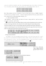
Page 16: ...ented by 0 time time zone longitude latitude and longitude can be modified or set Note 08 means the East eight 08 means the West eight other time zones and so on After the setting is completed press MENU to return until whether to save the setting interface Then select whether to save the data by pressing the left or right keys and press the return key to confirm and exit the setting interface 5 3...

Page 17: ...g to the channel the timing to the channel the second interface can set or modify the channel to be controlled 1 means that the channel is enabled 0 means that the channel is not enabled After the setting is completed press MENU to return until whether to save the setting interface Then select whether to save the data by pressing the left or right button and press Enter to confirm and exit the set...

Page 18: ...le 1 Set the regular time task and close all the channels at 18 00 every day After the setting is completed press MENU to return until whether to save the setting interface select Yes by pressing the left or right button and press Enter to confirm the saving of data and exit the setting interface Press the MENU key After entering the password press the Enter key to Press the left key or the right ...

Page 19: ... 0001 and press the enter key to enter After the password is correct enter the programming interface Press the left key or right key to switch the linkage setting and press the return key to enter Under the Linkage Settings interface the linkage function of DI1 and DI2 can be set The Press the page flip button Press the left key or the right key to select the timing and press the return key Select...

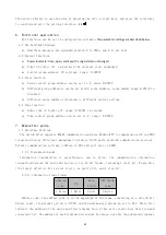
Page 20: ...and 13 24 channels 1 12 channels and 13 24 channels Mode is set to 010 After the setting is completed press MENU to return until whether to save the setting interface select Yes by pressing the left or right button and press Enter to confirm the saving of data and exit the setting interface 5 3 7 RS485 communication settings Press MENU to enter the programming password interface press the flip key...

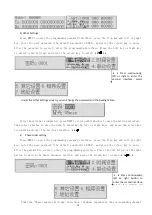
Page 21: ...e equipment information of the module the second interface displays the longitude and latitude and the corresponding sunrise and sunset time and the third interface displays the module communication information The fourth interface begins and displays the communication information of each slave module screen by screen 2 ALIBUS query Under the status display interface press the page turning key to ...

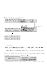
Page 22: ...ess the return key to confirm and exit the setting interface 4 Phase order setting Press MENU to enter the programming password interface press the flip key and left or right key enter the user password the default password is 0001 and press the return key to enter After the password is correct enter the programming interface Press the left button or the right button to switch the phase sequence s...

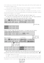
Page 23: ...ase voltage voltage frequency and total active energy The second interface displays the recorded channel number and the phase sequence current active power current harmonic content and active electric energy of the channel Press the left button or the right button to switch other channel power records 6 Change the physical address Press MENU to enter the programming password interface press the fl...

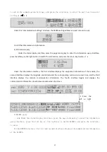
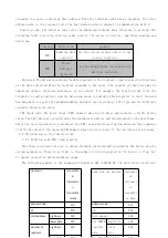
Page 24: ...s can be set in 3 range 0 65535 7 Newsletter guide 7 1 Interface Overview The switch drive supports RS485 communication and uses Modbus RTU to communicate with our EMS integrated energy efficiency management system or third party platform communication protocol Default communication settings address is 001 and port rate is 9600 7 1 1 Transmission mode Information transmission is asynchronous and i...

Page 25: ...bedded address and data vary according to the type and the different contents between the slave CRC check code The Error check CRC domain takes up two bytes and contains a 16 bit binary value The CRC values are calculated by the transmission device and then attached to the data frame where the receiving device recalculates the CRC value when receiving the data and then compares it with the values ...

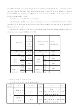
Page 26: ...t a time The following example is a switch driver with address 001 and baud rate 9600 channel 1 16 writes closed operation namely 0009H writes FFFF 7 3 Drive parameter address table 7 3 1 Drive real time status address table order number address parameter read w rite scale type 1 0x0000 high level year R W 0 99 Note Series 210 this address is reserved uint8 0x0000 low level moon R W 1 12 Note Seri...

Page 27: ... 210 this address is reserved uint8 4 0x0003 high level week R W The 0 6 stands for Sunday Saturday Note Series 210 this address is reserved uint8 0x0003 low level obligate uint8 5 0x0004 on off input R No input for bit0 0 and DI1 With bit0 1 DI1 has input No input for bit1 0 and that for DI2 Bit 1 1 and DI2 has input uint16 6 0x0005 Switch output R W Bit 0 0 and the DO 1 is not closed Bit 0 1 and...

Page 28: ...d the like 9 10 0x0008 Write to the fit state bit W The bit0 bit7 indicates the channel 17 24 and the maximum channel 24 Bit 0 1 10 close the channel 17 and the like uint32 0x0009 bit0 bit15 indicates channel 1 16 bit0 1 channel 1 and so on 11 12 0x000A Write to the fractional state bits W The bit0 bit7 indicates the channel 17 24 and the maximum channel 24 Bit 0 0 channel 17 points and the like u...

Page 29: ...9 156 0x006C 9B Channel 1 24 active electric energy R 3 decimal places in kWh uint32 157 204 0x009C CB Channel 1 24 Relay closing time R second uint32 205 288 0x00CC E3 Channel 1 24 relay closing times R Times uint16 229 231 0x00E4 E6 A B C phase voltage R At 1 decimal place in unit V Note Series 210 this address is reserved uint16 232 0x00E7 Voltage frequency R In 2 decimal places in the unit of ...

Page 30: ...W The bit0 bit7 indicates the channel 17 24 the maximum channel 24 Bit 0 0 Channel 17 is not enabled Bit 0 1 Enable channel 17 and the like uint32 6 0x0106 DI1 linkage switch association loop R W Bit 0 bit15 indicates channel 1 16 bit0 0 Channel 1 is not enabled Bit 0 1 Enable channel 1 and the like uint32 7 8 0x0107 DI1 linkage switch associated action value R W The bit0 bit7 indicates the channe...

Page 31: ...ved uint8 10 11 0x010A DI2 linkage switch association loop R W The bit0 bit7 indicates the channel 17 24 the maximum channel 24 Bit 0 0 Channel 17 is not enabled Bit 0 1 Enable channel 17 and the like Note Series 210 this address is reserved uint32 0x010B Blot 0 bit15 indicates lanes 1 16 Bit 0 0 Channel 1 is not enabled Bit 0 1 Enable channel 1 and the like Note Series 210 this address is reserve...

Page 32: ...ten specified time address table Note 210 Series this feature is not available number address parameter Read write scale type 1 2 0x1000 high level longitude R W 180 180 float 0x1001 low level 3 4 0x1002 high level latitude R W 90 90 float 0x1003 low level 5 0x1004 high level Sunrise time when R 0 23 uint8 0x1004 low level Sunrise time points 0 59 uint8 6 0x1005 high level Sunset time when R 0 23 ...

Page 33: ...that day uint8 0x1008 low level Timed Task 1 Execution Time when 0 23 stands for 0 23 24 for sunrise 25 for sunset uint8 10 0x1009 high level Timed task 1 Execution time points R W 0 59 uint8 0x1009 low level Execute the operation Timing task 1 Operation setting 00 minutes 01 close uint8 11 14 0x100A 0x100D The specific register meaning can refer to the timing task 1 15 18 0x100E 0x1011 The specif...

Page 34: ...D The specific register meaning can refer to the timing task 1 63 66 0x103E 0x1041 The specific register meaning can refer to the timing task 1 67 70 0x1042 0x1045 The specific register meaning can refer to the timing task 1 71 74 0x1046 0x1049 The specific register meaning can refer to the timing task 1 75 78 0x104A 0x104D The specific register meaning can refer to the timing task 1 79 82 0x104E ...

Page 35: ...an refer to the timing task 1 7 3 3 2 Scheduliming address table Note 210 Series this feature is not available number address parameter Read write scale type 1 2 0x1100 Schedule the timing task 1 loop setting R W The bit0 bit7 indicates the channel 17 24 the maximum channel 24 Bit 0 1 17 channel enabled timing Bit 0 0 Channel 17 is not enabled and so on uint32 0x1101 Blot 0 bit15 indicates lanes 1...

Page 36: ...36 40 0x1123 0x1127 Appointment timing task 8 Please refer to the appointment timing task 1 41 45 0x1128 0x112C Appointment timing task 9 Please refer to the appointment timing task 1 46 50 0x112D 0x1131 Appointment timing task 10 The specific register meaning may refer to the reservation timing task 1 51 55 0x1132 0x1136 The appointment timing task 11 Please refer to the appointment timing task 1...

Page 37: ...ment timing task 24 Please refer to reservation timing task 1 7 3 4 Event record address table 7 3 4 1 Record address table of opening machine Note 210 Series this feature is not available number address parameter Read write scale type 1 0x1200 high level year R 0 99 uint8 0x1200 low level moon R 1 12 uint8 2 0x1201 high level sun R 1 31 uint8 0x1201 low level time R 0 23 uint8 3 0x1202 high level...

Page 38: ... refer to the opening machine record 1 41 45 0x122A 0x122E The specific register meaning of the 9 can refer to the opening record 1 46 50 0x122F 0x1234 The specific register meaning of the opening record 10 may refer to the opening record 1 7 3 4 2 DIDO Record address table Note 210 Series this feature is not available number address parameter Read write scale type 1 0x1300 high level year R 0 99 ...

Page 39: ...ecord 1 7 3 4 3 Switrecord address table Note 210 Series this feature is not available number address parameter Read write scale type 1 0x1400 high level year R 0 99 uint8 0x1400 low level moon R 1 12 uint8 2 0x1401 high level sun R 1 31 uint8 0x1401 low level time R 0 23 uint8 3 0x1402 high level component R 0 59 uint8 0x1402 low level second R 0 59 uint8 4 0x1403 high level source R uint8 0x1403...

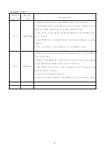
Page 40: ...ther the ALIBUS port is short circuit The data cannot be read through the RS485 interface ModBus _ RTU after power on please check whether the address and the port rate are consistent 9 matters need attention Before using the product please check whether the appearance is in good condition and find the seller in time if it is damaged Connect the wiring according to the instruction manual Check the...

Page 41: ... 4 New ASL220 series of power display function and channel recording function 5 New switch drive timing and DI setting address table V1 2 2022 09 26 1 Modify the shape and installation dimensions of the ASL220Z Sx 16 switch drive 2 Modify the ASL220Z Sx 16 switch driver electrical wiring diagram 3 New ASL210 main module dial code 7 8 function 4 New ASL220 switch drive other parameters and informat...

Reviews: