


10
removal.
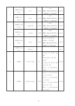
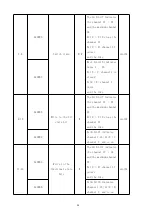
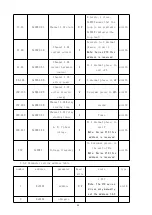
Step 1: open the linkage function, set it to mode 1:9,10 dial code to on terminal;
Step 2: Enable the 1-8 channel: register 0x0105,0x0106 write 0x0000,0x00ff;
Step 3: Set the 1-8 channel action value as 0: register 0x0107,0x0108 write 0x0000,0x00ff;
Note: The action value of "1" indicates the corresponding channel combination, and "0" indicates
the corresponding channel fraction
5.2.2 Description of the keys from the module
The control function can be realized from the module button: long press and short press.
Short press
In the control mode, the short press can be the channel full combination or
full split
Long press
After pressing the button for 3s, you can enter the control mode;
another 3s will exit the control mode
The control mode is also automatically withdrawn after 15s without
the operation
5.3 liquid crystal display
ASL220Z-Sx / 16, ASL220-Sx / 16 type comes with liquid crystal display, with switch drive status
query, information query, time and timing plan query and setting, DI / DO linkage query and setting,
RS485 communication function query and setting, other parameters query and setting.
5.3.1 Switch drive status query
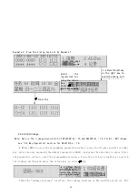
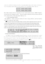
1) Power-on, shutdown and self-test
At the moment of power up, the switch drive interface is shown in the following figure, all
indicator lights turn on at the same time, the module conducts self-test, the interface is shown
in the following figure, all indicator lights are off in turn, and the final operation indicator
lights flicker to enter the normal monitoring state.
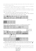
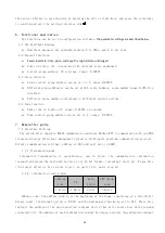
2) State display interface
After self-test, enter the state display interface. The first line shows the current date, week and time, and the
bottom two rows show the channel status, output (DO) and input (DI) status of each module respectively.
Note: □ represents DI disconnected, ■ represents DI closed, ○ represents DO disconnected, and
● represents DO closed.
0 means that the channel is divided, 1 means that the channel is closed, * the loop is not