20
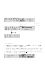
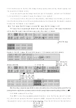
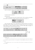
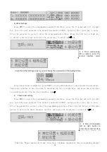
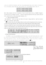
Then select whether to save the data by pressing the left or right keys, and press the return key
to confirm and exit the setting interface.
6. Functional application
All functions can be set in configuration software.
The parameter settings are described below
6.1 The heartbeat message
Heartbeat messages are uploaded between 0 to 255s, and 0 is not sent
6.2 General functions
Power loss state: close, open, and keep the original state unchanged
Power on state: off, on and keep the original state unchanged
Control group address: 10 settings, range: 0-65535
6.3 Scene function
Scene control group address can be set to 3, range 0-65535
Different group addresses can be set with 5 scene numbers, scene number range 0-255,0 is
disabled
Different scene numbers correspond to different control actions
6.4 Time function
Delay time of lights off: range: 0-65535 in seconds
Time control group address can be set in 3, range: 0-65535
7. Newsletter guide
7.1 Interface Overview
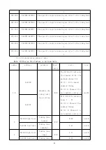
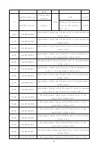
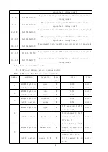
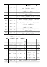
The switch drive supports RS485 communication and uses Modbus-RTU to communicate with our EMS
integrated energy efficiency management system or third-party platform communication protocol.
Default communication settings: address is 001 and port rate is 9600.
7.1.1 Transmission mode
Information transmission is asynchronous, and in bytes, the communication information
transmitted between the host and the slave is in 11-bit format, including 1 start bit, 8 data bits
(the lowest effective bit is sent first), no parity bit, and 1 stop bit.
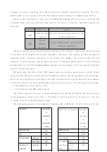
7.1.2, information frame format
address
code
FC
data
field
CRC check
code
1 Bytes
1 Bytes
n byte
2 Bytes
Address code: The address code is at the beginning of the frame, consisting of a byte (8-bit
binary code), the decimal system is 0~255, and the maximum system can be set to 247. These bits
indicate the address of the user-specified terminal device that will receive host data from and
connected to it. The address of each terminal device must be unique, and only the addressed terminal


