88
Chapter 3
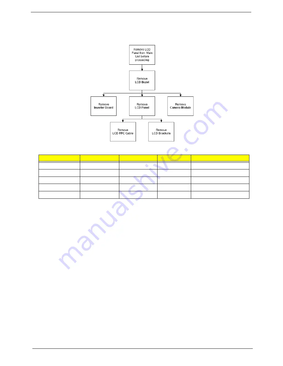
LCD Module Disassembly Process
LCD Module Disassembly Flowchart
Screw List
Step
Screw
Quantity
Color
Part No.
LCD Bezel
M2.5*5 (NL)
4
Black
MA000007YG0
Inverter Board
M2.5*5 (NL)
1
Black
MA000007YG0
Camera Module
M2*3 (NL)
2
Black
MA0000060G0
LCD Panel
M2.5*5 (NL)
2
Black
MA000007YG0
LCD Brackets
M2*3 (NL)
8
Black
MA0000060G0
Summary of Contents for TravelMate 4730 Series
Page 6: ...VI ...
Page 10: ...X Table of Contents ...
Page 14: ...4 Chapter 1 System Block Diagram ...
Page 34: ...24 Chapter 1 ...
Page 52: ...42 Chapter 2 ...
Page 60: ...50 Chapter 3 7 Remove the WLAN cover as shown ...
Page 95: ...Chapter 3 85 7 Lift the Thermal Module clear of the Mainboard ...
Page 114: ...104 Chapter 3 3 Connect the RJ 11 cable to the modem module as shown ...
Page 118: ...108 Chapter 3 2 Replace the two securing screws ...
Page 122: ...112 Chapter 3 2 Connect the seven cables on the mainboard as shown B C D E F G A ...
Page 128: ...118 Chapter 3 3 Turn the computer over and replace the five securing screws ...
Page 175: ...Chapter 6 165 ...
Page 184: ...Appendix A 174 ...
Page 188: ...178 Appendix B ...
Page 190: ...180 Appendix C ...
Page 193: ...183 Wireless Function Failure 136 WLAN Board 52 ...
Page 194: ...184 ...


