


18
Chapter 1
Hardware Specifications and Configurations
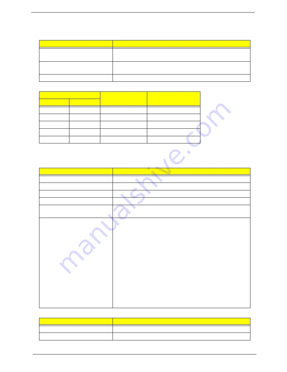
Processor
CPU Fan True Value Table
•
Throttling 50%: On= 100°C; OFF=90°C
•
OS shut down at 105°C; H/W shut down at 96°C
BIOS
Cache
Item
Specification
CPU type
Intel Cantiga GM / PM FSB: 667 / 800 / 1066 MHz
Intel Cantiga GL FSB: 667 MHz
Core logic
Intel® Core™2 Duo mobile processor, supporting Intel® 64
architecture
CPU package
Micro uPGA-478 Package
CPU Temperature
Fan Speed (RPM)
SPL Spec (dBA)
Core 0
Core 1
58
58
2500
29
66
66
3000
31
74
74
3400
34
85
85
3800
37
100
100
4200
40
Item
Specification
BIOS vendor Insyde
BIOS Version V1.00 (MP first release version; V1.07 latest version up to 0718.)
BIOS ROM type
Flash
BIOS ROM size
2MB
BIOS package
ACPI 2.0 compliance with Intel Speed Step Support C1, C2, C3,
C4, C6 and S3, S4 for mobile CPU
Supported protocols
•
Support ISIPP
•
Support Acer UI
•
Support multi-boot
•
Suspend to RAM (S3)/Disk (S4)
•
Various hot-keys for system control
•
Support SMBUS 2.0, PCI2.3
•
Support PXE
•
Support Y2K solution
•
Support Win Flash Wake on LAN from S3
•
Wake on LAN form S4 in AC mode
•
System information
•
Support ASF 2.0
•
Support iTPM (GM / PM Sku)
Item
Specification
Cache controller
CPU
Cache size
6MB L2 Cache on CPU
Summary of Contents for TravelMate 4730 Series
Page 6: ...VI ...
Page 10: ...X Table of Contents ...
Page 14: ...4 Chapter 1 System Block Diagram ...
Page 34: ...24 Chapter 1 ...
Page 52: ...42 Chapter 2 ...
Page 60: ...50 Chapter 3 7 Remove the WLAN cover as shown ...
Page 95: ...Chapter 3 85 7 Lift the Thermal Module clear of the Mainboard ...
Page 114: ...104 Chapter 3 3 Connect the RJ 11 cable to the modem module as shown ...
Page 118: ...108 Chapter 3 2 Replace the two securing screws ...
Page 122: ...112 Chapter 3 2 Connect the seven cables on the mainboard as shown B C D E F G A ...
Page 128: ...118 Chapter 3 3 Turn the computer over and replace the five securing screws ...
Page 175: ...Chapter 6 165 ...
Page 184: ...Appendix A 174 ...
Page 188: ...178 Appendix B ...
Page 190: ...180 Appendix C ...
Page 193: ...183 Wireless Function Failure 136 WLAN Board 52 ...
Page 194: ...184 ...


