84
Chapter 3
Removing the Thermal Module
1.
See “Removing the Battery Pack” on page 46.
2.
See “Removing the LCD Module” on page 65.
3.
See “Removing the Upper Cover” on page 67.
4.
See “Removing the Mainboard” on page 79.
5.
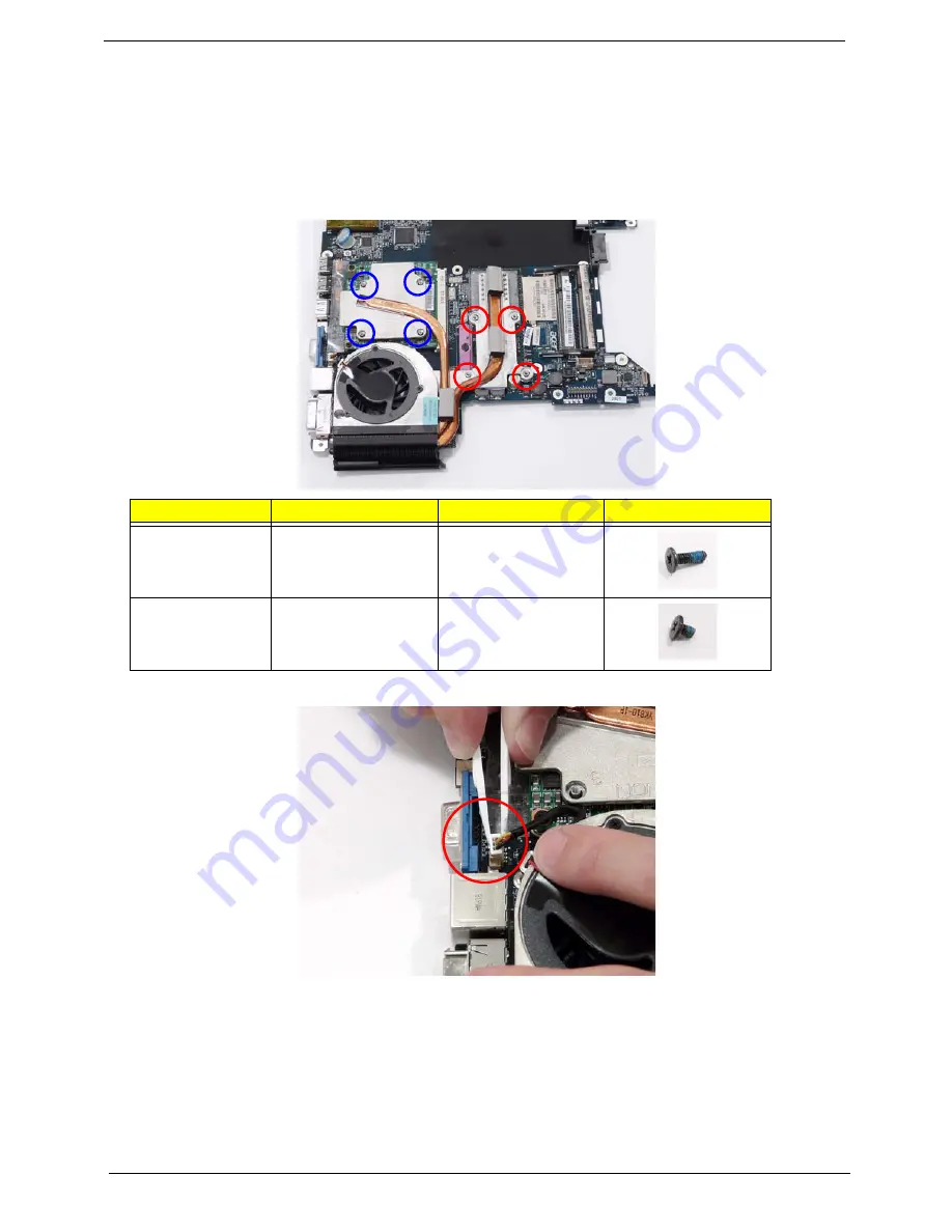
Remove the eight securing screws from the Thermal Modules.
6.
Disconnect the fan module cable from mainboard.
Step
Size
Quantity
Screw Type
CPU Thermal
Module
(red call out)
M2*6.5
4
VGA Thermal
Module
(blue call out)
M2*3
4
Summary of Contents for TravelMate 4730 Series
Page 6: ...VI ...
Page 10: ...X Table of Contents ...
Page 14: ...4 Chapter 1 System Block Diagram ...
Page 34: ...24 Chapter 1 ...
Page 52: ...42 Chapter 2 ...
Page 60: ...50 Chapter 3 7 Remove the WLAN cover as shown ...
Page 95: ...Chapter 3 85 7 Lift the Thermal Module clear of the Mainboard ...
Page 114: ...104 Chapter 3 3 Connect the RJ 11 cable to the modem module as shown ...
Page 118: ...108 Chapter 3 2 Replace the two securing screws ...
Page 122: ...112 Chapter 3 2 Connect the seven cables on the mainboard as shown B C D E F G A ...
Page 128: ...118 Chapter 3 3 Turn the computer over and replace the five securing screws ...
Page 175: ...Chapter 6 165 ...
Page 184: ...Appendix A 174 ...
Page 188: ...178 Appendix B ...
Page 190: ...180 Appendix C ...
Page 193: ...183 Wireless Function Failure 136 WLAN Board 52 ...
Page 194: ...184 ...


