background image

English 4

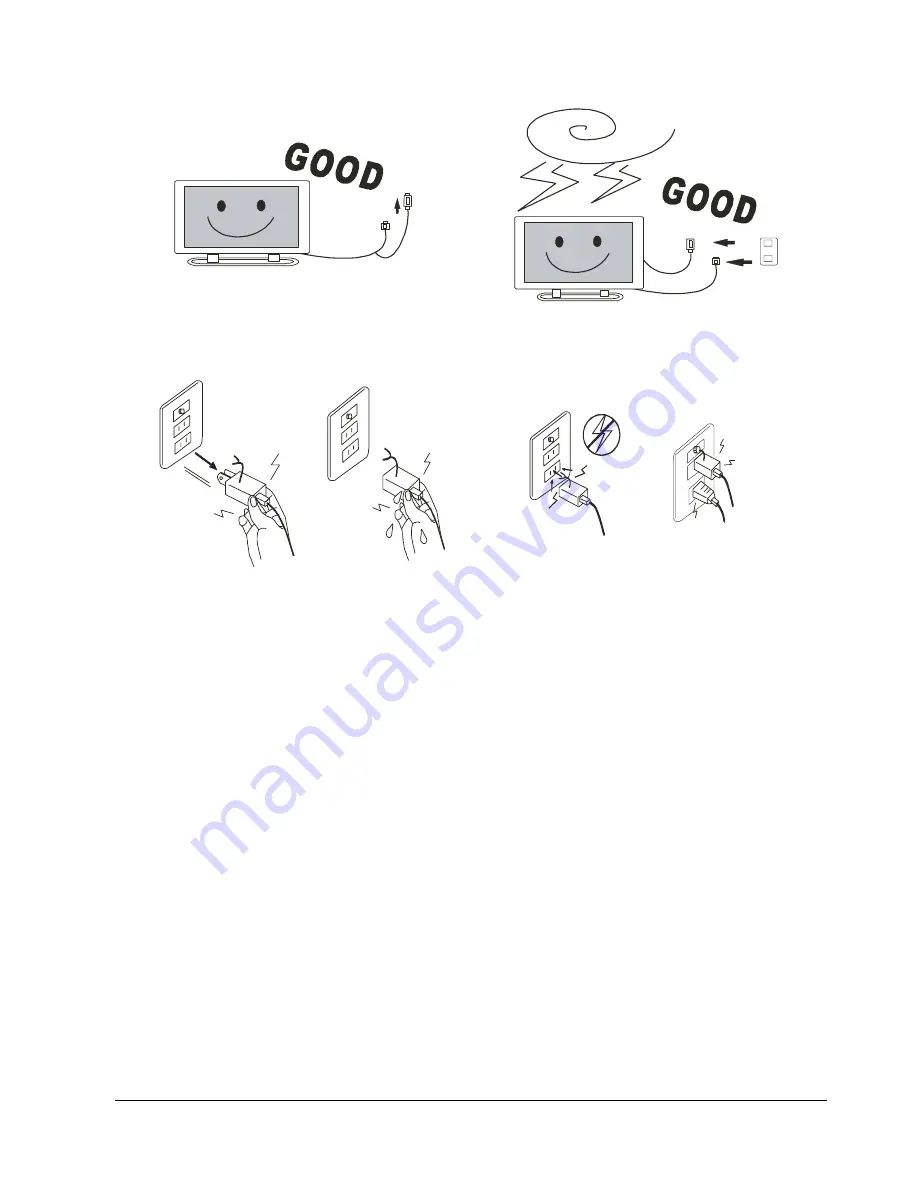
Electrical energy can perform many useful functions. This unit has been engineered and manufactured to 
assure your personal safety. But IMPROPER USE CAN RESULT IN POTENTIAL ELECTRICAL 
SHOCK OR FIRE HAZARD. In order not to defeat the safeguards incorporated into this product, 
observe the following basic rules for its installation, use and service. Please read these “Important 
Safeguards” carefully before use.

„

All the safety and operating instructions should be read before the product is operated.

„

The safety and operating instructions should be retained for future reference.

„

All warning on the product and in the operating instructions should be adhered to.

„

All operating instructions should be followed.

„

Unplug this product from the wall outlet before cleaning. Do not use liquid cleaners or aerosol 
cleaners. Use a damp cloth for cleaning.

„

Do not use attachments not recommended by the product manufacturer as they may cause hazards.

„

Do not use this product near water. Do not use immediately after moving from a low temperature to 
high temperature, as this causes condensation, which may result in fire, electric shock, or other 
hazards.

„

Do not place this product on an unstable cart, stand, or table. The product may fall, causing serious 
injury to a child or adult, and serious damage to the product. The product should be mounted 
according to the manufacturer’s instructions, and should use a mount recommended by the 
manufacturer.

Summary of Contents for PDP 7859

Page 1: ...V D SODVPD GLVSOD SDQHO DQG LV RQO FP GHHS LWK LWV KLJK LPDJH TXDOLW DQG SHUIRUPDQFH LW LV SHUIHFWO VXLWHG WR PXOWLPHGLD DSSOLFDWLRQV DQ UHFHLYH D YDULHW RI LQSXW VLJQDOV 9LGHR LQSXW PRGH 5 LQSXW PRGH 3RZHU 0DQDJHPHQW XQFWLRQ 5HPRWH 0RXVH XQFWLRQ Ù ...

Page 2: ...m 10 Remote Control 11 Putting Batteries In The Remote Control 13 Using the Remote Control 14 Effective Range For The Remote Control 14 CONNECTING DISPLAY TO EXTERNAL EQUIPMENT 15 BASIC OPERATIONS 16 TV Mode 17 PC Mode 19 Adjusting Function Mode 20 OSD Function Mode 21 OSD Function 21 1 Display 22 2 Image or TV System 22 3 Audio 23 4 Language 23 5 Misc 23 6 Status 24 Screen Function Mode 25 OPTION...

Page 3: ...talled and used in accordance with the instruction manual may cause harmful interference to radio communications Operation of this equipment in a residential area is likely to cause harmful interference in which case the user will be required to correct the interference at his own expense IMPORTANT INFORMATION SAFETY REGULATION WARNING This is a Class A product In a domestic environment this produ...

Page 4: ...English 3 oil ...

Page 5: ...in the operating instructions should be adhered to All operating instructions should be followed Unplug this product from the wall outlet before cleaning Do not use liquid cleaners or aerosol cleaners Use a damp cloth for cleaning Do not use attachments not recommended by the product manufacturer as they may cause hazards Do not use this product near water Do not use immediately after moving from ...

Page 6: ...rom the wall outlet and disconnect the cable system This will prevent damage to the product due to lightening and power line surges Do not overload wall outlets extension cords or convenience receptacles on other equipment as this can result in a risk of fire or electric shock Never push objects of any kind into this product through openings as they may touch dangerous voltage points or short out ...

Page 7: ... supply cord serves as a power disconnect device for plug able equipment The socket outlet shall be installed near the equipment and shall be easily accessible This display has a plasma display panel and is only 10 6 cm deep With its high image quality and performance it is perfectly suited to multimedia applications Can receive a variety of input signals In addition to video S video and RGB D SUB...

Page 8: ...reen W2 Non Linear W3 LetterBox W4 LetterBox SubTitle RGB input mode Two different screen sizes in RGB input mode 4 3 and 16 9 are also available Power Management Function The display features a DPMS Display Power Management Signaling function that ensures automatic power saving capability Remote Mouse Function You can operate the display by remote control using the PS2 interface Others You can sp...

Page 9: ...English 8 Accessories ...

Page 10: ...the display 2 Remote control signal receiver Receives signals from the remote control 3 Power Indicator Lamp This lamp shows whether the main power is ON or OFF as follows PART NAMES AND FUNCTIONS Lit Red Standby Lit Green Power ON Flashing Red Green flash respectively Power Saving mode ON ...

Page 11: ...lor difference output terminal of your DVD player 5 Audio input terminal 2 Connect this terminal to the sound output terminal of your VCR etc And this terminal is used for both AV3 Component Video Input 6 RGB input terminal RGB Input D sub Connect this terminal to the PC s display analog RGB output terminal 7 Audio input terminal 3 Connect this terminal to the sound output terminal of your PC 8 Re...

Page 12: ...Input Press this key to choose input source between PC TV AV AV also has Composite Video AV1 S Video AV2 Component Video AV3 3 TV CATV When input source is TV press this key to choose between TV Cable TV system Connect to Speaker 8 Ω 1 2 3 4 5 6 1 2 3 4 7 8 10 11 12 9 6 15 16 12 17 18 19 20 22 22 24 INPUT POWER SCAN CH MUTE MTS CH VOL DRAG AUTO CHRTN EXIT FREEZE ZOOM ZOOM OSD 100 RIGHT LEFT TV CAT...

Page 13: ...ormal situation 13 Volume a a a a b b b b Use these two hot keys to adjust volume straight and select sub menus while in OSD mode 14 Channel a a a a b b b b Use these two hot keys to select channel straight reserved in TV mode 15 Auto Press this key to auto adjust phase clock H V position in PC mode or to auto detect video system in TV AV mode 16 Number Keys Including number 0 1 2 3 4 5 6 7 8 9 Se...

Page 14: ...n The Remote Control 1 To remove the cover slide it outwards while pushing arrow bottom up 2 Put two AAA batteries in the remote control Make sure that the batteries are properly oriented 3 Close the cover until it snaps into place ...

Page 15: ...mote control and the display s signal receiver To prevent malfunction be sure not to apply any form of serve shock to the remote control And to prevent malfunction or deformation be sure not to allow the remote control to become wet also keep it away from hot locations or heating equipment Be sure not to clean the remote control using a cloth dampened in any volatile solvent such as benzene or thi...

Page 16: ...ing any connection Loose connectors can result in image or color problems Make sure that all connectors are securely inserted into their terminals CONNECTING DISPLAY TO EXTERNAL EQUIPMENT TV TV TV TV LD PC VCA S VGA XGA DVD VCR Camcorder LD PC VGA S VGA XGA DVD VCR Camcorder ...

Page 17: ...2 Display images from equipment connected to the S Video terminal AV3 Display images from equipment connected to the Component Video input terminal TV Display images only when a TV tuner card is connected to the cable TV terminal INPUT POWER SCAN CH MUTE MTS CH VOL DRAG AUTO CHRTN EXIT FREEZE ZOOM ZOOM OSD 100 RIGHT LEFT TV CATV DISPLAY INPUT POWER 1 2 3 1 2 3 1 2 3 1 2 3 4 5 6 4 5 6 4 5 6 4 5 6 0...

Page 18: ...INPUT POWER SCAN CH MUTE MTS CH VOL DRAG AUTO CHRTN EXIT FREEZE ZOOM ZOOM OSD 100 RIGHT LEFT TV CATV DISPLAY INPUT TV CATV DISPLAY INPUT INPUT POWER POWER SCAN SCAN CH CH MUTE MUTE MTS MTS CH CH VOL VOL DRAG DRAG AUTO AUTO CHRTN CHRTN EXIT EXIT FREEZE FREEZE ZOOM ZOOM ZOOM ZOOM OSD OSD 100 100 RIGHT RIGHT LEFT LEFT TV CATV TV CATV DISPLAY DISPLAY INPUT INPUT SCAN INPUT POWER SCAN CH MUTE MTS CH VO...

Page 19: ...igits press this key to input the first one digit Suppose the channel numbers are 125 at most MUTE INPUT POWER SCAN CH MUTE MTS CH VOL DRAG AUTO CHRTN EXIT FREEZE ZOOM ZOOM OSD 100 RIGHT LEFT TV CATV DISPLAY INPUT MTS INPUT POWER SCAN CH MUTE MTS CH VOL DRAG AUTO CHRTN EXIT FREEZE ZOOM ZOOM OSD 100 RIGHT LEFT TV CATV DISPLAY INPUT 1 2 3 4 5 6 INPUT POWER SCAN CH MUTE MTS CH VOL DRAG AUTO CHRTN EXI...

Page 20: ...ction as rolling ball at a mouse CHRTN INPUT POWER SCAN CH MUTE MTS CH VOL DRAG AUTO CHRTN EXIT FREEZE ZOOM ZOOM OSD 100 RIGHT LEFT TV CATV DISPLAY INPUT LEFT INPUT POWER SCAN CH MUTE MTS CH VOL DRAG AUTO CHRTN EXIT FREEZE ZOOM ZOOM OSD 100 RIGHT LEFT TV CATV DISPLAY INPUT INPUT POWER SCAN CH MUTE MTS CH VOL DRAG AUTO CHRTN EXIT FREEZE ZOOM ZOOM OSD 100 RIGHT LEFT TV CATV DISPLAY INPUT ...

Page 21: ...to decrease the volume Channel a a a a b b b b Use these two hot keys to select channel straight reserved in TV mode Press Channel a a a a to increase the channel Press Channel b b b b to decrease the channel RIGHT INPUT POWER SCAN CH MUTE MTS CH VOL DRAG AUTO CHRTN EXIT FREEZE ZOOM ZOOM OSD 100 RIGHT LEFT TV CATV DISPLAY INPUT DRAG INPUT POWER SCAN CH MUTE MTS CH VOL DRAG AUTO CHRTN EXIT FREEZE Z...

Page 22: ...out Green Sync adj Balance Italian High Brightness Blue Aspect Ratio Mute Spanish Color Temp Reset DPMS Simplified Chinese Reset to default Display TV System Audio Language Misc Brightness Aspect Ratio Volume English OSD H Positon Contrast Auto Treble French OSD V Position Sharpness NTSC Bass German OSD Timeout Hue PALM Balance Italian High Brightness Saturation PALN Mute Spanish Color Temp Reset ...

Page 23: ... in TV mode TV or AV input there will be Aspect ratio and different AV system source NTSC PAL M PAL N SECAM DPMS which stands for display power management signaling allows the display to maintain an automatic power saving function Auto Press this key to auto detect video system in TV AV mode to meet signal source system B C Brightness Contrast Red Green Blue Reset 75 55 20 18 60 B C Brightness Con...

Page 24: ...ified Chinese items 5 Misc When turn to Misc item either in PC or TV mode there will be OSD H Position OSD V Position OSD Timeout High Brightness Color Temp Reset to default The color temperature item in this OSD page is fixed on the three volumes Cool Standard and Warm B C Volume Treble ON OFF 50 55 66 20 Bass Mute Balance A B C OSD H Position OSD V Position OSD Timeout DPMS ON OFF Color Temp Res...

Page 25: ...y to pop up the OSD menu _ _ _ _ a a a a b b b b Left Right Up Down key Use the keys to adjust the OSD And the Right key also can work as the OSD enter function B C NTSC M 358 Video Info OSD INPUT POWER SCAN CH MUTE MTS CH VOL DRAG AUTO CHRTN EXIT FREEZE ZOOM ZOOM OSD 100 RIGHT LEFT TV CATV DISPLAY INPUT INPUT POWER SCAN CH MUTE MTS CH VOL DRAG AUTO CHRTN EXIT FREEZE ZOOM ZOOM OSD 100 RIGHT LEFT T...

Page 26: ...ify the screen EXIT INPUT POWER SCAN CH MUTE MTS CH VOL DRAG AUTO CHRTN EXIT FREEZE ZOOM ZOOM OSD 100 RIGHT LEFT TV CATV DISPLAY INPUT INPUT POWER SCAN CH MUTE MTS CH VOL DRAG AUTO CHRTN EXIT FREEZE ZOOM ZOOM OSD 100 RIGHT LEFT TV CATV DISPLAY INPUT ZOOM ZOOM INPUT POWER SCAN CH MUTE MTS CH VOL DRAG AUTO CHRTN EXIT FREEZE ZOOM ZOOM OSD 100 RIGHT LEFT TV CATV DISPLAY INPUT ...

Page 27: ...Function Press this key to hold on the screen the video source still runs Press again to continue FREEZE INPUT POWER SCAN CH MUTE MTS CH VOL DRAG AUTO CHRTN EXIT FREEZE ZOOM ZOOM OSD 100 RIGHT LEFT TV CATV DISPLAY INPUT ...

Page 28: ...tion as given in the relevant instruction manual are met Warning To prevent injury fire and electric shock arrange for options to be initially installed by your dealer OPTIONS Stand unit Wall mounting unit Fixed angle Wall mounting unit Adjustable angle 0 25 Ceiling mount Speaker Speaker Stand ...

Page 29: ...GS Resolution Horizontal Frequency KHz Vertical Frequency Hz Dot Clock Frequency MHz Remark 720 400 31 47 70 08 25 17 DOS 640 400 37 90 85 00 31 50 VESA 640 480 31 50 60 00 25 18 DOS 640 480 35 00 67 00 30 24 Mac SOG 640 480 37 50 75 00 31 50 VESA 640 480 37 86 72 81 31 50 VESA 640 480 43 30 85 00 36 00 VESA 800 600 35 16 56 25 36 00 VESA 800 600 37 90 60 32 40 00 VESA 800 600 46 90 75 00 49 50 VE...

Page 30: ...omposite Video input S Video input Component Video input and RGB input Colors 16 77 million for each of 256 RGB gradations Gray scale level 256 8 bit color for each R G B Brightness 260 cd m2 panel only Contrast Ratio 450 1 panel only with Vsync 60 Hz Viewing Angle Over 160º Operating Conditions Temperature 0 to 45 C Humidity 20 to 85 Total Weight 33 6 Kg without stand Power Supply 90 264V Power C...

Page 31: ...wer cannot be turned on Check whether the power plug is securely inserted into the receptacle No images are displayed Check the cable for disconnection Check whether the power for all input equipment is ON Check for connection to wrong terminal or for wrong input mode Remote control does not function properly Check for incorrect battery orientation Check for dead batteries Check for distance from ...

Page 32: ...for proper input mode If the power indicator lamp flashes red and green respectively Check the cable for disconnection Check whether the screen is on power saving status See P 9 Power Indicator Lamp If Out of range appears the display is receiving a signal whose image or signal cannot be reproduced by the display Input the proper signals See P 28 FACTORY SETTINGS ...

Reviews: