


Chapter 2
31
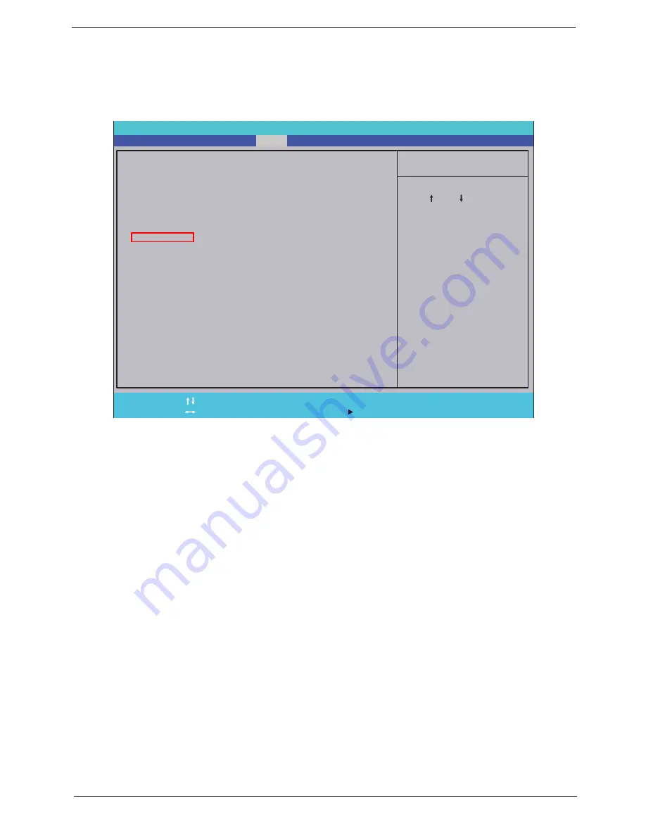
Boot
This menu allows the user to decide the order of boot devices to load the operating system. Bootable devices
includes the USB diskette drives, the onboard hard disk drive and the DVD drive in the module bay.
Select Boot menu to select specific devices to support boot.
I t e m S p e c i f i c H e l p
U s e < > o r < > t o s e l e c t
a d e v i c e , t h e n p r e s s
< F 5 > t o m o v e i t d o w n t h e
l i s t , o r < F 6 > t o m o v e
i t u p t h e l i s t . P r e s s
< E s c > t o e s c a p e t h e m e n u
F 1
E S C
H e l p
E x i t
S e l e c t I t e m
S e l e c t M e n u
C h a n g e Va l u e s
S e l e c t
S u b M e n u
E n t e r
F 9
F 1 0
S e t u p D e f a u l t
S a v e a n d E x i t
B o o t p r i o r i t y o r d e r :
1 . N e t w o r k B o o t : L E G A C Y P C I D E V I C E
2 . U S B F D D :
3 . I D E 0 : S T 9 2 5 0 3 1 5 A S
4 . U S B H D D :
5 . U S B C D / D V D R O M :
6 . I D E 1 : S l i m t y p e D V D A D S 8 A 4 S H
B o o t p r i o r i t y o r d e r :
1 . N e t w o r k B o o t : L E G A C Y P C I D E V I C E
2 . U S B F D D :
3 . I D E 0 : S T 9 2 5 0 3 1 5 A S
4 . U S B H D D :
5 . U S B C D / D V D R O M :
6 . I D E 1 : S l i m t y p e D V D A D S 8 A 4 S H
F 5 / F 6
I n s y d e H 2 0 S e t u p U t i l i t y R e v . 3 . 5
Information
Main
Boot
Exit
Security
Summary of Contents for LX.PWJ02.001
Page 6: ...VI ...
Page 10: ...X Table of Contents ...
Page 34: ...24 Chapter 1 ...
Page 52: ...42 Chapter 2 ...
Page 76: ...66 Chapter 3 5 Lift the Speaker clear of the Upper Cover ...
Page 78: ...68 Chapter 3 5 Lift the Right Speaker Module clear of the device ...
Page 84: ...74 Chapter 3 5 Lift the USB board clear of the device ...
Page 90: ...80 Chapter 3 11 Disconnect the Bluetooth to mainboard cable ...
Page 92: ...82 Chapter 3 4 Carefully lift the Thermal Module clear of the Mainboard ...
Page 103: ...Chapter 3 93 7 Disconnect the LVDS cable from the panel ...
Page 105: ...Chapter 3 95 5 Lift the microphone set and cable clear of the LCD cover ...
Page 121: ...Chapter 3 111 5 Connect the fan cable ...
Page 124: ...114 Chapter 3 6 Connect the LVDS cable to the mainboard 7 Connect the microphone cable ...
Page 127: ...Chapter 3 117 4 Connect the USB cable to the mainboard and lock the connector ...
Page 130: ...120 Chapter 3 4 Replace the FFC and press down as indicated to secure it to the Upper Cover ...
Page 146: ...136 Chapter 3 ...
Page 175: ...Chapter 6 165 Aspire 5251 5551G 5551 FRU List ...
Page 176: ...166 Chapter 6 Screw List ...
Page 177: ...Chapter 6 167 ...
Page 206: ...196 Appendix C ...
Page 210: ...200 ...