Theory of Operation
4-19
8-, 16-, and 32-bit cards using full 32-bit PCI cycles for maximum performance.
Independent 32-bit write buffers allow fast-posted writes to improve system-bus
utilization.
An advanced CMOS process is used to achieve low system-power consumption while
operating at PCI clock rates up to 33 MHz. Several low-power modes allow the host
power-management system to further reduce power consumption.
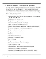
4.2.10.1 PCI 1130 Features
♦
3.3V core logic with universal PCI interface compatible with 3.3V or 5V PCI
signaling environments
♦
Supports PCI Local Bus specification 2.1
♦
Mix and match 3.3V/5V PC card 16 cards and 3.3V CardBus cards
♦
Supports two PC card or CardBus slots with hot insertion and removal
♦
1995 PC Card standard compliant
♦
Low-Power advanced submicron CMOS technology
♦
Uses serial interface to Texas Instruments (TI) tps2202a dual power switch
♦
System interrupts can be programmed as PCI-Style or ISA IRQ-Style interrupts
♦
ISA IRQ interrupts can be serialized onto a single IRQSER pin
♦
Independent read and write buffers for each direction
♦
Supports burst transfers to maximize data throughput on the PCI and CardBus
bus
♦
Multifunction PCI device with separate five PCI Memory Windows and two I/O
Windows available to each PC Card 16 socket
♦
Two l/O Windows and two memory windows available to each CardBus socket
♦
CardBus Memory Windows can be individually selected prefetchable or non-
PREFETCHABLE
♦
ExchangeableCard (ExCAT)-compatible registers are mapped in memory and
I/O space
♦
TI extension registers are mapped in the PCI configuration space
♦
Intel 82365SL DF register compatible
♦
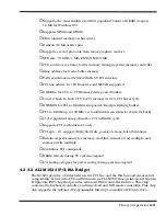
Supports 16-bit distributed Direct Memory Access (DMA) on both PC Card
sockets
Summary of Contents for Extensa 900 Series
Page 1: ...Maintenance Manual ExtensaTM 900 Series Notebook Computers 9813715 0001 December 1996 ...
Page 10: ......
Page 28: ......
Page 44: ......
Page 56: ......
Page 82: ......
Page 98: ......
Page 138: ...A 2 Notebook Schematic Diagrams Figure A 1 Notebook Main Board Logic Diagrams Sheet 1 of 30 ...
Page 139: ...Notebook Schematic Diagrams A 3 Figure A 1 Notebook Main Board Logic Diagrams Sheet 2 of 30 ...
Page 140: ...A 4 Notebook Schematic Diagrams Figure A 1 Notebook Main Board Logic Diagrams Sheet 3 of 30 ...
Page 141: ...Notebook Schematic Diagrams A 5 Figure A 1 Notebook Main Board Logic Diagrams Sheet 4 of 30 ...
Page 142: ...A 6 Notebook Schematic Diagrams Figure A 1 Notebook Main Board Logic Diagrams Sheet 5 of 30 ...
Page 143: ...Notebook Schematic Diagrams A 7 Figure A 1 Notebook Main Board Logic Diagrams Sheet 6 of 30 ...
Page 145: ...Notebook Schematic Diagrams A 9 Figure A 1 Notebook Main Board Logic Diagrams Sheet 8 of 30 ...
Page 146: ...A 10 Notebook Schematic Diagrams Figure A 1 Notebook Main Board Logic Diagrams Sheet 9 of 30 ...
Page 147: ...Notebook Schematic Diagrams A 11 Figure A 1 Notebook Main Board Logic Diagrams Sheet 10 of 30 ...
Page 148: ...A 12 Notebook Schematic Diagrams Figure A 1 Motherboard PWB Logic Diagrams Sheet 11 of 23 ...
Page 149: ...Notebook Schematic Diagrams A 13 Figure A 1 Notebook Main Board Logic Diagrams Sheet 12 of 30 ...
Page 153: ...Notebook Schematic Diagrams A 17 Figure A 1 Notebook Main Board Logic Diagrams Sheet 16 of 30 ...
Page 154: ...A 18 Notebook Schematic Diagrams Figure A 1 Notebook Main Board Logic Diagrams Sheet 17 of 30 ...
Page 155: ...Notebook Schematic Diagrams A 19 Figure A 1 Notebook Main Board Logic Diagrams Sheet 18 of 30 ...
Page 156: ...A 20 Notebook Schematic Diagrams Figure A 1 Notebook Main Board Logic Diagrams Sheet 19 of 30 ...
Page 157: ...Notebook Schematic Diagrams A 21 Figure A 1 Notebook Main Board Logic Diagrams Sheet 20 of 30 ...
Page 158: ...A 22 Notebook Schematic Diagrams Figure A 1 Notebook Main Board Logic Diagrams Sheet 21 of 30 ...
Page 159: ...Notebook Schematic Diagrams A 23 Figure A 1 Notebook Main Board Logic Diagrams Sheet 22 of 30 ...
Page 160: ...A 24 Notebook Schematic Diagrams Figure A 1 Notebook Main Board Logic Diagrams Sheet 23 of 30 ...
Page 161: ...Notebook Schematic Diagrams A 25 Figure A 1 Notebook Main Board Logic Diagrams Sheet 24 of 30 ...
Page 166: ...A 30 Notebook Schematic Diagrams Figure A 1 Notebook Main Board Logic Diagrams Sheet 29 of 30 ...
Page 168: ......
Page 171: ...MPB Schematic Diagrams B 3 Figure B 1 MPB CPU Board Logic Diagrams Sheet 2 of 3 ...
Page 176: ...B 8 MPB Schematic Diagrams Figure B 3 MPB Main Board Motherboard Logic Diagrams Sheet 3 of 10 ...
Page 196: ......
Page 197: ......
Page 198: ......


