POST BIOS
C-3
; Display prompt "Press F2 to enter SETUP"
;----------------------------------------------------------------------------
04BH quiet Boot Start, OPTIONAL, FAR
04EH post Copyright Display, FAR
050H
cpu Display, FAR
051H
eisa Init, OPTIONAL
05AH post Display F2 Message, FAR
;----------------------------------------------------------------------------
; Disable the CPU cache
; Size and test the system memory
; Size and test the extended memory
; Test extended memory address lines
; User hook # 1
;----------------------------------------------------------------------------
05BH cpu Cache Off
05CH post Memory Test, FAR
060H
post Extended Memory Test, FAR
062H
post Extended Address Test, FAR
064H
user Patch1
;----------------------------------------------------------------------------
; Enable and configure the cache
; Display the cache size if a cache was detected and enabled.
; Display size of shadow RAM, size of non-disposable BIOS
;----------------------------------------------------------------------------
066H
cache Adv Config
068H
cache Configure
06AH post Display Cache Size, FAR
06CH post Display Shadows, FAR
06EH post Display Non Disposable, FAR
;----------------------------------------------------------------------------
; Display any POST errors
; Check for configuration errors
; Test Real Time Clock
; Check for keyboard errors
;----------------------------------------------------------------------------
070H
post Display Error Messages, FAR
072H
post Test Config, FAR
074H
post RTC Test, FAR
;----------------------------------------------------------------------------
; Set up hardware interrupt vectors
; Test coprocessor if present
; Return to standard real mode
;----------------------------------------------------------------------------
07CH post Setup Hardware Vectors, FAR
07EH cpu Coprocessor Test, FAR
096H
post Clear Huge ES
;----------------------------------------------------------------------------
; Disable programmable I/O devices
; Detect and install fixed RS232 ports
; Detect and install fixed parallel ports
; Init PC-compatible PNP & PCI devices (COM, LPT, floppy, etc.)
; Re-enable programmable I/O and check for conflicts with fixed I/O
;----------------------------------------------------------------------------
post Shutdown Eight Table LABEL post Proc
Summary of Contents for Extensa 900 Series
Page 1: ...Maintenance Manual ExtensaTM 900 Series Notebook Computers 9813715 0001 December 1996 ...
Page 10: ......
Page 28: ......
Page 44: ......
Page 56: ......
Page 82: ......
Page 98: ......
Page 138: ...A 2 Notebook Schematic Diagrams Figure A 1 Notebook Main Board Logic Diagrams Sheet 1 of 30 ...
Page 139: ...Notebook Schematic Diagrams A 3 Figure A 1 Notebook Main Board Logic Diagrams Sheet 2 of 30 ...
Page 140: ...A 4 Notebook Schematic Diagrams Figure A 1 Notebook Main Board Logic Diagrams Sheet 3 of 30 ...
Page 141: ...Notebook Schematic Diagrams A 5 Figure A 1 Notebook Main Board Logic Diagrams Sheet 4 of 30 ...
Page 142: ...A 6 Notebook Schematic Diagrams Figure A 1 Notebook Main Board Logic Diagrams Sheet 5 of 30 ...
Page 143: ...Notebook Schematic Diagrams A 7 Figure A 1 Notebook Main Board Logic Diagrams Sheet 6 of 30 ...
Page 145: ...Notebook Schematic Diagrams A 9 Figure A 1 Notebook Main Board Logic Diagrams Sheet 8 of 30 ...
Page 146: ...A 10 Notebook Schematic Diagrams Figure A 1 Notebook Main Board Logic Diagrams Sheet 9 of 30 ...
Page 147: ...Notebook Schematic Diagrams A 11 Figure A 1 Notebook Main Board Logic Diagrams Sheet 10 of 30 ...
Page 148: ...A 12 Notebook Schematic Diagrams Figure A 1 Motherboard PWB Logic Diagrams Sheet 11 of 23 ...
Page 149: ...Notebook Schematic Diagrams A 13 Figure A 1 Notebook Main Board Logic Diagrams Sheet 12 of 30 ...
Page 153: ...Notebook Schematic Diagrams A 17 Figure A 1 Notebook Main Board Logic Diagrams Sheet 16 of 30 ...
Page 154: ...A 18 Notebook Schematic Diagrams Figure A 1 Notebook Main Board Logic Diagrams Sheet 17 of 30 ...
Page 155: ...Notebook Schematic Diagrams A 19 Figure A 1 Notebook Main Board Logic Diagrams Sheet 18 of 30 ...
Page 156: ...A 20 Notebook Schematic Diagrams Figure A 1 Notebook Main Board Logic Diagrams Sheet 19 of 30 ...
Page 157: ...Notebook Schematic Diagrams A 21 Figure A 1 Notebook Main Board Logic Diagrams Sheet 20 of 30 ...
Page 158: ...A 22 Notebook Schematic Diagrams Figure A 1 Notebook Main Board Logic Diagrams Sheet 21 of 30 ...
Page 159: ...Notebook Schematic Diagrams A 23 Figure A 1 Notebook Main Board Logic Diagrams Sheet 22 of 30 ...
Page 160: ...A 24 Notebook Schematic Diagrams Figure A 1 Notebook Main Board Logic Diagrams Sheet 23 of 30 ...
Page 161: ...Notebook Schematic Diagrams A 25 Figure A 1 Notebook Main Board Logic Diagrams Sheet 24 of 30 ...
Page 166: ...A 30 Notebook Schematic Diagrams Figure A 1 Notebook Main Board Logic Diagrams Sheet 29 of 30 ...
Page 168: ......
Page 171: ...MPB Schematic Diagrams B 3 Figure B 1 MPB CPU Board Logic Diagrams Sheet 2 of 3 ...
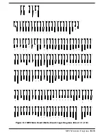
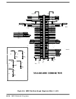
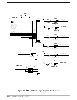
Page 176: ...B 8 MPB Schematic Diagrams Figure B 3 MPB Main Board Motherboard Logic Diagrams Sheet 3 of 10 ...
Page 196: ......
Page 197: ......
Page 198: ......


