Theory of Operation
4-23
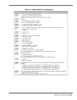
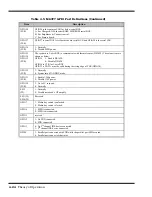
Table 4-5 M6377 GPIO Port Definitions
Item
Description
GPIO17
(W/R)
1: Connect serial BUS with charger ROM.
0: Disconnect serial BUS with charger ROM.
GPIO20 is the CLK and GPIO21 is the DATA for the serial BUS.
GPIO16
Reserved
GPIO15
(W/R)
1: CPU high temperature SMI is allowed.
0: CPU low temperature SMI is allowed.
GPIO14
(W/R)
1: Connect the ZV BUS with PCMCIA card.
0: Connect the ZV BUS with Feature board.
GPIO13
(W)
1: Force the system to enter 0V suspend or power down mode, and then could press power
button to turn on system again.
0: Normal
GPIO12
(W/R)
1: Force FAN on
0: Normally
GPIO11
(W/R)
1: 12V power foor FLASH ROM.
0: 12V power.
GPIO10
(W/R)
1: Disable FIR VCC.
0: Enable FIR VCC.
GPIO27
(R)
1: CPU high temperature.
0: CPU low temperature.
GPIO26
(W/R)
1: notebook’s SMBUS is accessible.
0: MPB’s SMBUS is accessible.
GPIO25
(W/R)
1: Brightness level is fixed
0: Brightness is trimable via GPIO22 & GPIO20.
The current brightness level is stored when PIO25 low to high transations.
GPIO24
(W/R)
For DSTN LCD only.
1: Contrast level is fixed.
0: Contrast is trimable via GPIO22 & GPIO20.
The current brightness level is stored when PIO25 low to high transations.
GPIO23
1: Normally
0: Ready to transations.
GPIO22
(W/R)
The Brightness & Contrast for LCD system is devided into 32 scale by programing GPIO22 &
GPIO20.
1: Brightness is incremented with GPIO23 “L” and GPIO20 high to low transations.
Contrast is incremented with GPIO24 :L” and GPIO20 high to low transations.
0: Brightness is decremented with GPIO24 “L” and GPIO20 high to low transations.
Contrast is decremented with GPIO23 “L” and GPIO20 high to low transations.
GPIO21
(W/R)
The system provide a serial BUS while wired to Inverter ROM, notebook’s Charger ROM, MPB’s
Charger ROM and Uma’s dock ROM.
GPIO21 is the serial DAT and GPIO20 is the serial CLK.
Summary of Contents for Extensa 900 Series
Page 1: ...Maintenance Manual ExtensaTM 900 Series Notebook Computers 9813715 0001 December 1996 ...
Page 10: ......
Page 28: ......
Page 44: ......
Page 56: ......
Page 82: ......
Page 98: ......
Page 138: ...A 2 Notebook Schematic Diagrams Figure A 1 Notebook Main Board Logic Diagrams Sheet 1 of 30 ...
Page 139: ...Notebook Schematic Diagrams A 3 Figure A 1 Notebook Main Board Logic Diagrams Sheet 2 of 30 ...
Page 140: ...A 4 Notebook Schematic Diagrams Figure A 1 Notebook Main Board Logic Diagrams Sheet 3 of 30 ...
Page 141: ...Notebook Schematic Diagrams A 5 Figure A 1 Notebook Main Board Logic Diagrams Sheet 4 of 30 ...
Page 142: ...A 6 Notebook Schematic Diagrams Figure A 1 Notebook Main Board Logic Diagrams Sheet 5 of 30 ...
Page 143: ...Notebook Schematic Diagrams A 7 Figure A 1 Notebook Main Board Logic Diagrams Sheet 6 of 30 ...
Page 145: ...Notebook Schematic Diagrams A 9 Figure A 1 Notebook Main Board Logic Diagrams Sheet 8 of 30 ...
Page 146: ...A 10 Notebook Schematic Diagrams Figure A 1 Notebook Main Board Logic Diagrams Sheet 9 of 30 ...
Page 147: ...Notebook Schematic Diagrams A 11 Figure A 1 Notebook Main Board Logic Diagrams Sheet 10 of 30 ...
Page 148: ...A 12 Notebook Schematic Diagrams Figure A 1 Motherboard PWB Logic Diagrams Sheet 11 of 23 ...
Page 149: ...Notebook Schematic Diagrams A 13 Figure A 1 Notebook Main Board Logic Diagrams Sheet 12 of 30 ...
Page 153: ...Notebook Schematic Diagrams A 17 Figure A 1 Notebook Main Board Logic Diagrams Sheet 16 of 30 ...
Page 154: ...A 18 Notebook Schematic Diagrams Figure A 1 Notebook Main Board Logic Diagrams Sheet 17 of 30 ...
Page 155: ...Notebook Schematic Diagrams A 19 Figure A 1 Notebook Main Board Logic Diagrams Sheet 18 of 30 ...
Page 156: ...A 20 Notebook Schematic Diagrams Figure A 1 Notebook Main Board Logic Diagrams Sheet 19 of 30 ...
Page 157: ...Notebook Schematic Diagrams A 21 Figure A 1 Notebook Main Board Logic Diagrams Sheet 20 of 30 ...
Page 158: ...A 22 Notebook Schematic Diagrams Figure A 1 Notebook Main Board Logic Diagrams Sheet 21 of 30 ...
Page 159: ...Notebook Schematic Diagrams A 23 Figure A 1 Notebook Main Board Logic Diagrams Sheet 22 of 30 ...
Page 160: ...A 24 Notebook Schematic Diagrams Figure A 1 Notebook Main Board Logic Diagrams Sheet 23 of 30 ...
Page 161: ...Notebook Schematic Diagrams A 25 Figure A 1 Notebook Main Board Logic Diagrams Sheet 24 of 30 ...
Page 166: ...A 30 Notebook Schematic Diagrams Figure A 1 Notebook Main Board Logic Diagrams Sheet 29 of 30 ...
Page 168: ......
Page 171: ...MPB Schematic Diagrams B 3 Figure B 1 MPB CPU Board Logic Diagrams Sheet 2 of 3 ...
Page 176: ...B 8 MPB Schematic Diagrams Figure B 3 MPB Main Board Motherboard Logic Diagrams Sheet 3 of 10 ...
Page 196: ......
Page 197: ......
Page 198: ......

