


6-14
FRU (Field Replaceable Unit) List
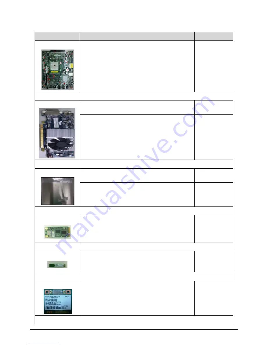
Mainboard aBoston AMD A75 Realtek RTL8111E-VL
Acer Logo Proprietary W/O 1394 V1.0 LF w/
MCR/USB3.0/SPIDF, for UMA and switchable VGA
MB.SHQ0P.001
VGA CARD
288-1E181-M01AC HD6570 1GB DDR3 128bits DVI-I
(DL) + HDMI SAMSUNG Blower No Bkt LP
VG.PC657.A01
288-1E181-N01AC HD6570 1GB DDR3 128bits DVI-I
(DL) + HDMI HYNIX Blower No Bkt LP
VG.PC657.A02
Panel
LCD 21.5 IN. LPL LM215WF4 TLE7 W/ TOUCH
PANEL MODULE
6M.SHP0U.002
LED LCD LPL 21.5''W FHD None Glare LM215WF4
TLE7 LF 250nit 5ms Fab P8
LK.21508.014
TV-Tuner
AverMedia A373-2D Kits TV Tuner Card
TU.10500.089
TU.10500.091
Bluetooth
BT USB BM-GP-BR-55 MODULE
BT.14500.009
WLAN
WLAN MINI WN6602RH-AA 802.11BGN
NI.10200.034
Camera
Table 6-2. FRU list
Category
Description
P/N
Summary of Contents for Aspire Z3170
Page 1: ...Acer AZ3170 AZ3171 SERVICEGUIDE ...
Page 2: ...ii ...
Page 6: ...1 iv ...
Page 7: ...CHAPTER 1 Hardware Specifications ...
Page 26: ...1 20 Hardware Specifications and Configurations M B Placement 0 ...
Page 29: ...Hardware Specifications and Configurations 1 23 Block Diagram 0 ...
Page 30: ...1 24 Hardware Specifications and Configurations ...
Page 31: ...CHAPTER 2 System Utilities ...
Page 36: ...2 6 System Utilities Advanced 0 Advanced Miscellaneous 0 ...
Page 48: ...2 18 System Utilities 8 Flash BIOS is finished ...
Page 52: ...2 22 System Utilities 10 Flash BIOS is finished ...
Page 55: ...System Utilities 2 25 11 Select Yes and press Enter key 12 Flash BIOS is finished ...
Page 58: ...2 28 System Utilities ...
Page 62: ...2 32 System Utilities ...
Page 63: ...CHAPTER 3 System Disassembly and Assembly ...
Page 66: ...3 4 ...
Page 74: ...3 12 System Disassembly and Assembly First open one top side then open the other top side ...
Page 75: ...System Disassembly and Assembly 3 13 Open the low side ...
Page 85: ...System Disassembly and Assembly 3 23 Removing the Display Card 0 Unplug the DVI cable ...
Page 97: ...System Disassembly and Assembly 3 35 Remove the CPU ...
Page 103: ...System Disassembly and Assembly 3 41 ...
Page 111: ...System Disassembly and Assembly 3 49 Unplug the LCD power cable Take out the LCD with bracket ...
Page 121: ...System Disassembly and Assembly 3 59 Lock all the latch Plug the LVDS cable ...
Page 131: ...System Disassembly and Assembly 3 69 Table 3 35 ID Size Quantity Screw Type M4 6L K 4 ...
Page 138: ...3 76 System Disassembly and Assembly Plug the DVI cable and lock 2 VGA locks ...
Page 145: ...System Disassembly and Assembly 3 83 Attach the mylar to cover the camera ...
Page 152: ...3 90 System Disassembly and Assembly 4 Attach the mylar as the location shown in the picture ...
Page 156: ...3 94 System Disassembly and Assembly N A 4 Table 3 45 ID Size Quantity Screw Type ...
Page 162: ...3 100 System Disassembly and Assembly Install the hinge cover ...
Page 163: ...System Disassembly and Assembly 3 101 Thermal Pad location on base pan 0 ...
Page 165: ...System Disassembly and Assembly 3 103 AMD 6570 0 Attach the thermal pad on VGA memories ...
Page 166: ...3 104 System Disassembly and Assembly ...
Page 167: ...CHAPTER 4 Troubleshooting ...
Page 183: ...Troubleshooting 4 17 Pressing the 25 calibration points in proper hole by using the stylus ...
Page 187: ...CHAPTER 5 Jumper and Connector Locations ...
Page 188: ...5 2 Jumper Setting 5 4 Setting Jumper 5 4 ...
Page 189: ...Jumper and Connector Locations 5 3 Jumper and Connector Locations ...
Page 192: ...5 6 Jumper and Connector Locations ...
Page 193: ...CHAPTER 6 FRU List ...
Page 194: ...6 2 AZ3170 AZ3171 Exploded Diagrams 6 4 FRU List 6 6 ...


