


System Disassembly and Assembly
3-53
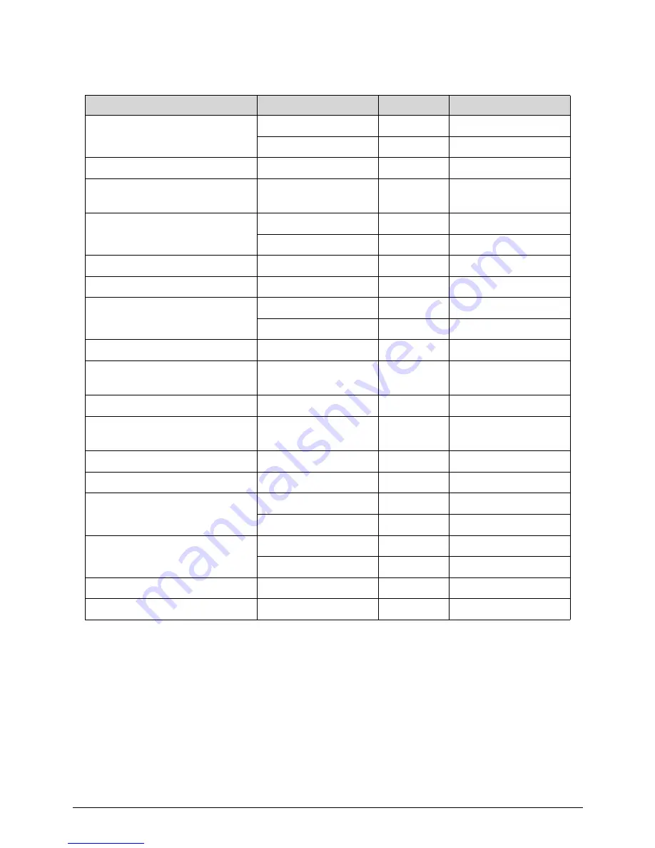
Table 3-25. Screw list
Step
Screw
Quantity
Acer Part Number
Replacing the LCD
M3X5L (B)
4
86.GBL0U.001
M3*4L (B)
2
86.U6N0U.006
Replacing the Base Pan
M3X5L (B)
11
86.GBL0U.001
Replacing the Left & Right Foot
Stand (Power LED)
M3X5L (B)
16
86.GBL0U.001
Replacing the System Fan
M4*6L (B)
4
86.U6N0U.007
M3X5L (B)
3
86.GBL0U.001
Replacing the Motherboard
M3X5L (B)
8
86.GBL0U.001
Replacing the Speaker
M3*4L+5.1 (X)
4
86.U6N0U.009
Replacing the TV Tuner
M2*4L (K)
2
86.U6N0U.003
M3X5L (B)
1
86.GBL0U.001
Replacing the WLAN
M2*4L (K)
2
86.U6N0U.003
Replacing the Touchpad Control
Board
M3X5L (B)
2
86.GBL0U.001
Replacing the Heatsink
M3X5L (B)
1
86.GBL0U.001
Replacing the Motherboard
Shielding
M3X5L (B)
9
86.GBL0U.001
Replacing the Converter Board
M3X5L (B)
2
86.GBL0U.001
Replacing the OSD Board
M3X5L (B)
2
86.GBL0U.001
Replacing the ODD
M3X5L (B)
1
86.GBL0U.001
M2*2L (K)
4
86.U6N0U.001
Replacing the HDD
M3X5L (B)
1
86.GBL0U.001
#6-32*3.6+3.8L
4
86.U6N0U.008
Replacing the Rear Cover
M3*8.0L (P)
7
86.U6N0U.005
Replacing the Stand
M4*8L (F)
3
86.U6Q0U.001
Summary of Contents for Aspire Z3170
Page 1: ...Acer AZ3170 AZ3171 SERVICEGUIDE ...
Page 2: ...ii ...
Page 6: ...1 iv ...
Page 7: ...CHAPTER 1 Hardware Specifications ...
Page 26: ...1 20 Hardware Specifications and Configurations M B Placement 0 ...
Page 29: ...Hardware Specifications and Configurations 1 23 Block Diagram 0 ...
Page 30: ...1 24 Hardware Specifications and Configurations ...
Page 31: ...CHAPTER 2 System Utilities ...
Page 36: ...2 6 System Utilities Advanced 0 Advanced Miscellaneous 0 ...
Page 48: ...2 18 System Utilities 8 Flash BIOS is finished ...
Page 52: ...2 22 System Utilities 10 Flash BIOS is finished ...
Page 55: ...System Utilities 2 25 11 Select Yes and press Enter key 12 Flash BIOS is finished ...
Page 58: ...2 28 System Utilities ...
Page 62: ...2 32 System Utilities ...
Page 63: ...CHAPTER 3 System Disassembly and Assembly ...
Page 66: ...3 4 ...
Page 74: ...3 12 System Disassembly and Assembly First open one top side then open the other top side ...
Page 75: ...System Disassembly and Assembly 3 13 Open the low side ...
Page 85: ...System Disassembly and Assembly 3 23 Removing the Display Card 0 Unplug the DVI cable ...
Page 97: ...System Disassembly and Assembly 3 35 Remove the CPU ...
Page 103: ...System Disassembly and Assembly 3 41 ...
Page 111: ...System Disassembly and Assembly 3 49 Unplug the LCD power cable Take out the LCD with bracket ...
Page 121: ...System Disassembly and Assembly 3 59 Lock all the latch Plug the LVDS cable ...
Page 131: ...System Disassembly and Assembly 3 69 Table 3 35 ID Size Quantity Screw Type M4 6L K 4 ...
Page 138: ...3 76 System Disassembly and Assembly Plug the DVI cable and lock 2 VGA locks ...
Page 145: ...System Disassembly and Assembly 3 83 Attach the mylar to cover the camera ...
Page 152: ...3 90 System Disassembly and Assembly 4 Attach the mylar as the location shown in the picture ...
Page 156: ...3 94 System Disassembly and Assembly N A 4 Table 3 45 ID Size Quantity Screw Type ...
Page 162: ...3 100 System Disassembly and Assembly Install the hinge cover ...
Page 163: ...System Disassembly and Assembly 3 101 Thermal Pad location on base pan 0 ...
Page 165: ...System Disassembly and Assembly 3 103 AMD 6570 0 Attach the thermal pad on VGA memories ...
Page 166: ...3 104 System Disassembly and Assembly ...
Page 167: ...CHAPTER 4 Troubleshooting ...
Page 183: ...Troubleshooting 4 17 Pressing the 25 calibration points in proper hole by using the stylus ...
Page 187: ...CHAPTER 5 Jumper and Connector Locations ...
Page 188: ...5 2 Jumper Setting 5 4 Setting Jumper 5 4 ...
Page 189: ...Jumper and Connector Locations 5 3 Jumper and Connector Locations ...
Page 192: ...5 6 Jumper and Connector Locations ...
Page 193: ...CHAPTER 6 FRU List ...
Page 194: ...6 2 AZ3170 AZ3171 Exploded Diagrams 6 4 FRU List 6 6 ...


