


4-6
Troubleshooting
Checkpoints
0
A checkpoint is either a byte or word value output to I/O port 80h. The BIOS outputs
checkpoints throughout boot-block and Power-On Self Test (POST) to indicate the task the
system is currently executing. Checkpoint share very useful in aiding software developers or
technicians in debugging problems that occur during the pre- boot process.
Viewing BIOS checkpoints
0
Viewing all checkpoints generated by the BIOS requires a checkpoint card, also referred to
as a POST card or POST diagnostic card. These are ISA or PCI add-in cards that show the
value of I/O port 80h on a LED display. Checkpoints may appear on the bottom right corner of
the screen during POST. This display method is limited, since it only displays checkpoints that
occur after the video card has been activated.
Bootblock Initialization Code Checkpoints
0
The Bootblock initialization code sets up the chipset, memory, and other components before
system is available. The following table describes the type of checkpoints that may occur
during the bootblock initialization portion of the BIOS.
NOTE:
NOTE
:
Please note that checkpoints may differ between different platforms based on system
configuration. Checkpoints may change due to vendor requirements, system chipset or
option ROMs from add-in PCI devices.
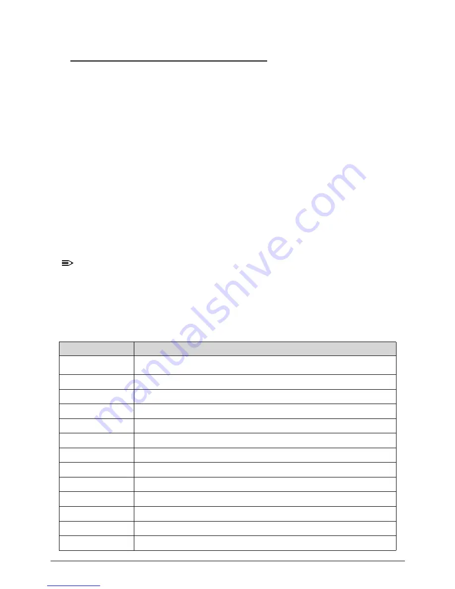
SEC Status Codes
0
Table 4-2.
Checkpoint
Description
0x00
Not Used
0x01
Power on. Reset type detection (soft/hard).
0x02
AP initialization before microcode loading
0x03
North Bridge initialization before microcode loading
0x04
South Bridge initialization before microcode loading
0x05
OEM initialization before microcode loading
0x06
Microcode loading
0x07
AP initialization after microcode loading
0x08
North Bridge initialization after microcode loading
0x09
South Bridge initialization after microcode loading
0x0A
OEM initialization after microcode loading
0x0B
Cache initialization
0x0C – 0x0D
Reserved for future AMI SEC error codes
Summary of Contents for Aspire Z3170
Page 1: ...Acer AZ3170 AZ3171 SERVICEGUIDE ...
Page 2: ...ii ...
Page 6: ...1 iv ...
Page 7: ...CHAPTER 1 Hardware Specifications ...
Page 26: ...1 20 Hardware Specifications and Configurations M B Placement 0 ...
Page 29: ...Hardware Specifications and Configurations 1 23 Block Diagram 0 ...
Page 30: ...1 24 Hardware Specifications and Configurations ...
Page 31: ...CHAPTER 2 System Utilities ...
Page 36: ...2 6 System Utilities Advanced 0 Advanced Miscellaneous 0 ...
Page 48: ...2 18 System Utilities 8 Flash BIOS is finished ...
Page 52: ...2 22 System Utilities 10 Flash BIOS is finished ...
Page 55: ...System Utilities 2 25 11 Select Yes and press Enter key 12 Flash BIOS is finished ...
Page 58: ...2 28 System Utilities ...
Page 62: ...2 32 System Utilities ...
Page 63: ...CHAPTER 3 System Disassembly and Assembly ...
Page 66: ...3 4 ...
Page 74: ...3 12 System Disassembly and Assembly First open one top side then open the other top side ...
Page 75: ...System Disassembly and Assembly 3 13 Open the low side ...
Page 85: ...System Disassembly and Assembly 3 23 Removing the Display Card 0 Unplug the DVI cable ...
Page 97: ...System Disassembly and Assembly 3 35 Remove the CPU ...
Page 103: ...System Disassembly and Assembly 3 41 ...
Page 111: ...System Disassembly and Assembly 3 49 Unplug the LCD power cable Take out the LCD with bracket ...
Page 121: ...System Disassembly and Assembly 3 59 Lock all the latch Plug the LVDS cable ...
Page 131: ...System Disassembly and Assembly 3 69 Table 3 35 ID Size Quantity Screw Type M4 6L K 4 ...
Page 138: ...3 76 System Disassembly and Assembly Plug the DVI cable and lock 2 VGA locks ...
Page 145: ...System Disassembly and Assembly 3 83 Attach the mylar to cover the camera ...
Page 152: ...3 90 System Disassembly and Assembly 4 Attach the mylar as the location shown in the picture ...
Page 156: ...3 94 System Disassembly and Assembly N A 4 Table 3 45 ID Size Quantity Screw Type ...
Page 162: ...3 100 System Disassembly and Assembly Install the hinge cover ...
Page 163: ...System Disassembly and Assembly 3 101 Thermal Pad location on base pan 0 ...
Page 165: ...System Disassembly and Assembly 3 103 AMD 6570 0 Attach the thermal pad on VGA memories ...
Page 166: ...3 104 System Disassembly and Assembly ...
Page 167: ...CHAPTER 4 Troubleshooting ...
Page 183: ...Troubleshooting 4 17 Pressing the 25 calibration points in proper hole by using the stylus ...
Page 187: ...CHAPTER 5 Jumper and Connector Locations ...
Page 188: ...5 2 Jumper Setting 5 4 Setting Jumper 5 4 ...
Page 189: ...Jumper and Connector Locations 5 3 Jumper and Connector Locations ...
Page 192: ...5 6 Jumper and Connector Locations ...
Page 193: ...CHAPTER 6 FRU List ...
Page 194: ...6 2 AZ3170 AZ3171 Exploded Diagrams 6 4 FRU List 6 6 ...


