


Troubleshooting
4-9
Bootblock Recovery Code Checkpoints
0
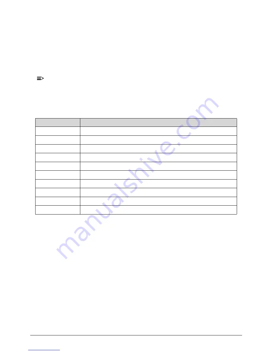
The Bootblock recovery code gets control when the BIOS determines that a BIOS recovery
needs to occur because the user has forced the update or the BIOS checksum is corrupt. The
following table describes the type of checkpoints that may occur during the Bootblock
recovery portion of the BIOS.
NOTE:
NOTE
:
Checkpoints may differ between different platforms based on system configuration.
Checkpoints may change due to vendor requirements, system chipset or option ROMs
from add-in PCI devices
Checkpoint
Description
0xF0
Recovery condition triggered by firmware (Auto recovery)
0xF1
Recovery condition triggered by user (Forced recovery)
0xF2
Recovery process started
0xF3
Recovery firmware image is found
0xF4
Recovery firmware image is loaded
0xF5-0xF7
Reserved for future AMI progress codes
0xF8
Recovery PPI is not available
0xF9
Recovery capsule is not found
0xFA
Invalid recovery capsule
0xFB– 0xFF
Reserved for future AMI error codes
Summary of Contents for Aspire Z3170
Page 1: ...Acer AZ3170 AZ3171 SERVICEGUIDE ...
Page 2: ...ii ...
Page 6: ...1 iv ...
Page 7: ...CHAPTER 1 Hardware Specifications ...
Page 26: ...1 20 Hardware Specifications and Configurations M B Placement 0 ...
Page 29: ...Hardware Specifications and Configurations 1 23 Block Diagram 0 ...
Page 30: ...1 24 Hardware Specifications and Configurations ...
Page 31: ...CHAPTER 2 System Utilities ...
Page 36: ...2 6 System Utilities Advanced 0 Advanced Miscellaneous 0 ...
Page 48: ...2 18 System Utilities 8 Flash BIOS is finished ...
Page 52: ...2 22 System Utilities 10 Flash BIOS is finished ...
Page 55: ...System Utilities 2 25 11 Select Yes and press Enter key 12 Flash BIOS is finished ...
Page 58: ...2 28 System Utilities ...
Page 62: ...2 32 System Utilities ...
Page 63: ...CHAPTER 3 System Disassembly and Assembly ...
Page 66: ...3 4 ...
Page 74: ...3 12 System Disassembly and Assembly First open one top side then open the other top side ...
Page 75: ...System Disassembly and Assembly 3 13 Open the low side ...
Page 85: ...System Disassembly and Assembly 3 23 Removing the Display Card 0 Unplug the DVI cable ...
Page 97: ...System Disassembly and Assembly 3 35 Remove the CPU ...
Page 103: ...System Disassembly and Assembly 3 41 ...
Page 111: ...System Disassembly and Assembly 3 49 Unplug the LCD power cable Take out the LCD with bracket ...
Page 121: ...System Disassembly and Assembly 3 59 Lock all the latch Plug the LVDS cable ...
Page 131: ...System Disassembly and Assembly 3 69 Table 3 35 ID Size Quantity Screw Type M4 6L K 4 ...
Page 138: ...3 76 System Disassembly and Assembly Plug the DVI cable and lock 2 VGA locks ...
Page 145: ...System Disassembly and Assembly 3 83 Attach the mylar to cover the camera ...
Page 152: ...3 90 System Disassembly and Assembly 4 Attach the mylar as the location shown in the picture ...
Page 156: ...3 94 System Disassembly and Assembly N A 4 Table 3 45 ID Size Quantity Screw Type ...
Page 162: ...3 100 System Disassembly and Assembly Install the hinge cover ...
Page 163: ...System Disassembly and Assembly 3 101 Thermal Pad location on base pan 0 ...
Page 165: ...System Disassembly and Assembly 3 103 AMD 6570 0 Attach the thermal pad on VGA memories ...
Page 166: ...3 104 System Disassembly and Assembly ...
Page 167: ...CHAPTER 4 Troubleshooting ...
Page 183: ...Troubleshooting 4 17 Pressing the 25 calibration points in proper hole by using the stylus ...
Page 187: ...CHAPTER 5 Jumper and Connector Locations ...
Page 188: ...5 2 Jumper Setting 5 4 Setting Jumper 5 4 ...
Page 189: ...Jumper and Connector Locations 5 3 Jumper and Connector Locations ...
Page 192: ...5 6 Jumper and Connector Locations ...
Page 193: ...CHAPTER 6 FRU List ...
Page 194: ...6 2 AZ3170 AZ3171 Exploded Diagrams 6 4 FRU List 6 6 ...


