background image

Machine Maintenance

3-23

4.

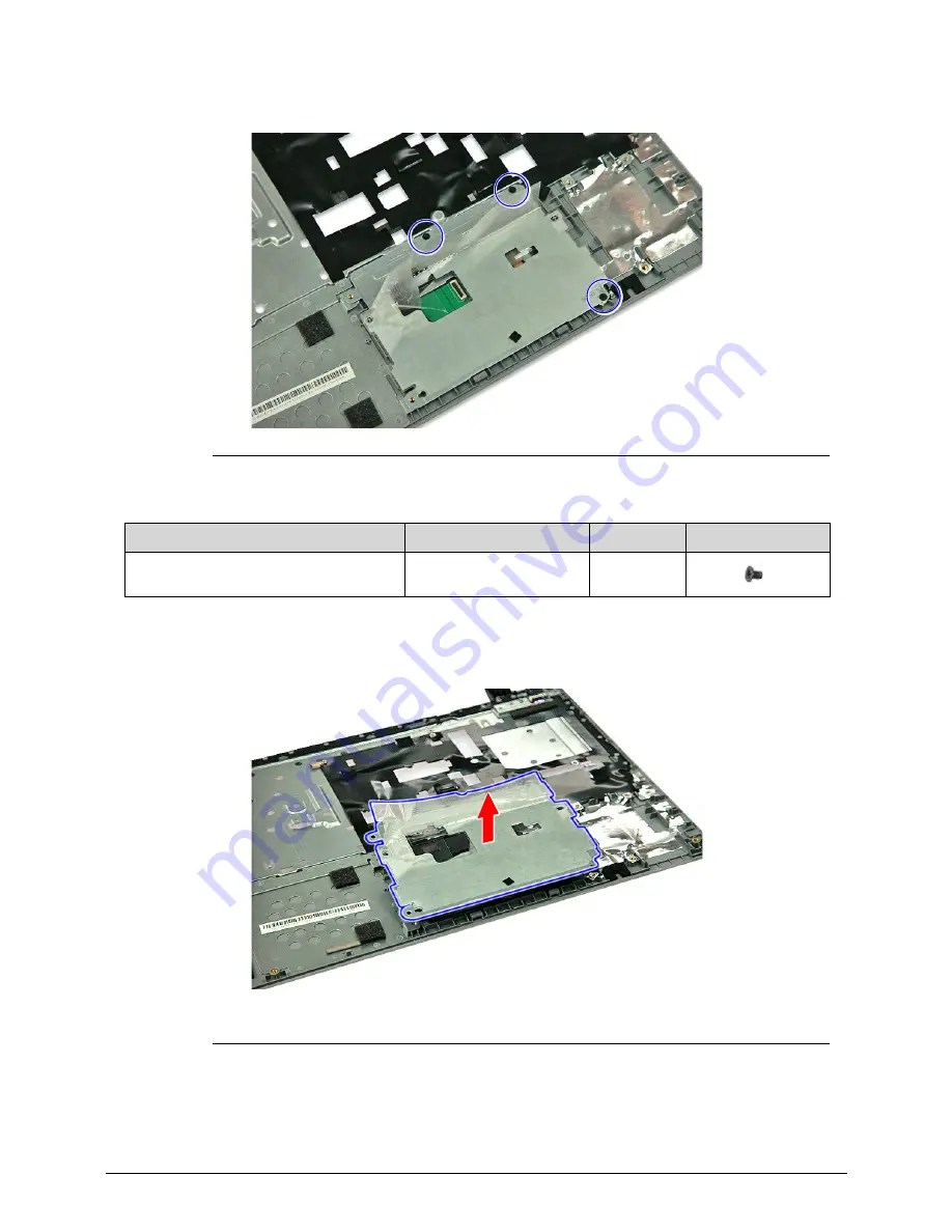
Remove the three screws securing the touchpad board to the upper case assembly.

Figure 3-25.

Touchpad Screws

5.

Detach the touchpad bracket from the upper case assembly.

Figure 3-26.

Touchpad Bracket

Table 3-25.

Screws

Step

Screw

Quantity

Screw Type

Touchpad Module Disassembly

M2 × L3

3

Summary of Contents for Aspire V5-571P

Page 1: ...Aspire V5 571PG V5 571P SERVICEGUIDE ...

Page 2: ... the programs prove defective following their purchase the buyer not the manufacturer distributor or its dealer assumes the entire cost of all necessary servicing repair and any incidental or consequential damages resulting from any defect in the software Copyright 2012 by Acer Incorporated All rights reserved No part of this publication may be reproduced transmitted transcribed stored in a retrie...

Page 3: ...rocess names are shown in italics Example the DRS5 User s Guide usr local bin fd the TPH15spool_M program Computer output text that represents information displayed on a computer screen such as menus prompts responses to input and error messages are shown in constant width Example 01 The server has been stopped User input text that represents information entered by a computer user such as command ...

Page 4: ...These localized features are not covered in this generic service guide In such cases contact your regional office or the responsible personnel channel to provide you with further technical details When ordering FRU parts Check the most up to date information available on your regional Web or channel If for whatever reason a part number change is made it may not be noted in this printed service gui...

Page 5: ...I O Ports 1 8 Software and Tools 1 8 Warranty 1 10 Dimensions and Weight 1 10 Environment 1 10 Notebook Tour 1 11 Open Front View 1 11 Close Front View 1 12 Left View 1 13 Right View 1 14 Base View 1 15 Touchpad Basics 1 16 Keyboard 1 17 System Block Diagram 1 21 Specification Tables 1 22 Chapter 2 System Utilities BIOS Setup Utility 2 3 Navigating the BIOS Utility 2 3 BIOS Menus 2 4 Information 2...

Page 6: ...DD Module 3 15 Main Unit Disassembly Process 3 18 Main Unit Disassembly Flowchart 3 18 Removing the Palmrest Module Upper Case 3 19 Removing the Touchpad Board 3 22 Removing the Power Button Board 3 25 Removing the SATA Board 3 27 Removing the HDD Module 3 28 Removing the WLAN Module 3 29 Removing the Mainboard 3 31 Removing the Thermal Module 3 35 Removing the DC In Module 3 37 Removing the Batte...

Page 7: ...rmal Module 3 74 Reinstalling the Mainboard 3 76 Reinstalling the WLAN Module 3 81 Reinstalling the HDD Module 3 83 Reinstalling the SATA Board 3 84 Reinstalling the Power Button Board 3 85 Reinstalling the Touchpad Board 3 87 Reinstalling the Palmrest Module Upper Case 3 90 External Module Reassembly Process 3 92 Reinstalling the ODD Module 3 92 Reinstalling the Keyboard 3 95 Reinstalling the DIM...

Page 8: ... 25 Chapter 5 Jumper and Connector Locations Mainboard Layout 5 3 Clearing Password Check and BIOS Recovery 5 5 Clearing the BIOS Passwords 5 5 Performing a BIOS Recovery 5 6 Chapter 6 FRU Field Replaceable Unit List Exploded Diagrams 6 4 Main Assembly 6 4 LCD Assembly 6 6 Chapter 7 Test Compatible Components Microsoft Windows 8 Environment Test 7 3 Chapter 8 Online Support Information ...

Page 9: ...CHAPTER 1 Hardware Specifications ...

Page 10: ...t 1 10 Environment 1 10 Notebook Tour 1 11 Open Front View 1 11 Close Front View 1 12 Left View 1 13 Right View 1 14 Base View 1 15 Touchpad Basics 1 16 Keyboard 1 17 System Block Diagram 1 21 Specification Tables 1 22 Computer Specifications 1 22 Processor 1 23 Processor Specifications 1 24 System Memory 1 25 Graphics Controller 1 26 VRAM Discrete models only 1 26 System BIOS 1 26 Keyboard 1 27 H...

Page 11: ... Interface 1 30 Webcam 1 30 LAN 1 31 Wireless LAN 1 31 USB Interface 1 31 HDMI Port 1 32 Expansion Card 1 32 System LED Indicators 1 32 Battery Pack 1 32 AC Adapter 1 33 System Power Management 1 34 System DMA Specification 1 34 ...

Page 12: ...1 4 ...

Page 13: ...ssional 64 bit Platform 0 Intel Chief River Supports the Second Generation Intel Core Mobile Processor Family Ivy Bridge Sandy Bridge Chipset Mobile Intel HM70 HM77 Express Chipset System Memory 0 Two DDR3 1333 MHz DIMM slots 8 GB maximum memory capacity using two 4 GB modules Supports dual channel Display 0 15 6 inch High Definition WXGA LED Touch Panel Integrated multi touch screen supports 10 f...

Page 14: ...isk drive 0 2 5 inch 7 0 mm 5400 rpm SATA hard disk drive HDD Optical disc drive 0 Slim type SATA optical disc drive ODD Detailed read write specifications on page 1 28 Card reader 0 Multi in 1 card reader slot Supports MultiMediaCard MMC MultiMediaCard Plus MMCplus Memory Stick MS Memory Stick PRO MS PRO xD Picture Card xD and Secure Digital SD cards Audio Subsystem 0 Optimized Dolby Advanced Aud...

Page 15: ...Nplify 802 11a b g n Wi Fi CERTIFIED Supports Acer SignalUp wireless technology LAN on Feature Port thru bundled Y Cable Gigabit Ethernet Wake on LAN ready Realtek RTL8411AA CG controller Privacy Control 0 BIOS supervisor user and HDD passwords Kensington lock slot Power Adapter and Battery 0 19 V 3 pin 65 W AC adapter 4 Cell 2 5 Ah Li ion battery pack Battery life 4 hours Charging period 1 5 to 2...

Page 16: ...inting device Touchpad lock hotkey Adjustable touchpad sensitivity function I O Ports 0 Multi in 1 card reader SD MMC MS XD USB ports 2 x 2 0 1 x 3 0 HDMI port with HDCP support Headphones speaker line out jack without S PDIF support Internal microphone Feature port bundled Y cable with LAN VGA combo port DC in jack for AC adapter Kensington lock slot Software and Tools 0 Productivity 0 7digital A...

Page 17: ...NTI Media Maker Cyberlink MediaEspresso Gaming 0 Cut the Rope Pinball FX2 Treasures of Montezuma Communication and ISP 0 Acer Crystal Eye Skype Web links and utilities 0 Acer Accessory Store Belgium France Germany Italy Netherlands Spain Sweden UK only Acer Explorer Acer Identity Card Acer Updater eBay shortcut Australia Austria Canada France Germany Italy India Ireland Mexico Netherlands Philippi...

Page 18: ...ht 0 Dimensions 0 Width Depth Height 381 6 x 253 x 24 5mm 15 02 9 96 0 96 in Weight 0 2 44 kg 5 38 lb including battery for UMA models 2 48 kg 5 47 lb including battery for Discrete models Environment 0 Temperature Operating 0 to 40 C Non operating 20 to 60 C Humidity non condensing Operating 20 to 80 Non operating 20 to 80 ...

Page 19: ...nication 2 Touch display screen Also called liquid crystal display LCD displays computer output supports multi touch input 3 Integrated microphone Internal microphone for sound recording and video communication 4 Palmrest Comfortable support area for your hands when you use the computer 5 Touchpad Touch sensitive pointing device which functions like a computer mouse 6 Keyboard For entering data in...

Page 20: ...ports MMC MMCplus and SD cards Note Only one card can operate at any given time 2 Power indicator Indicates the computer s power status Blue The computer is turned on Blinking amber The computer is in power saving mode 3 Battery indicator Indicates the computer s battery status Blue The computer is in AC mode Blinking amber The battery is charging ...

Page 21: ...er 2 Feature port Connects to a Y cable with VGA RJ45 port 3 HDMI port Supports high definition digital video connections 4 USB 3 0 ports Connects to USB devices e g USB mouse USB camera 5 USB 2 0 ports Connects to USB devices e g USB mouse USB camera 6 Headphones speaker line out jack Connects to audio line out devices e g speakers headphone ...

Page 22: ...s the optical disc from the drive 4 ODD emergency eject hole Insert a paper clip to the emergency eject hole to eject the optical drive tray when the computer is off 5 Kensington lock slot Connects to a Kensington compatible computer security lock Note Wrap the computer security lock cable around an immovable object such as a table or the handle of a locked drawer Insert the lock into the notch an...

Page 23: ...cription 1 Battery pack Provides power to the computer when the power cord is unplugged 2 Battery release latch Releases the battery for removal 3 DIMM compartment Houses the computer s memory modules 4 Speaker Outputs sounds 5 Optical disc drive ODD Internal optical disc drive accepts CDs or DVDs ...

Page 24: ... located beneath the touchpad to perform selection and execution functions These two buttons are the equivalent of the left and right buttons on a mouse Function Touchpad 1 Left Button 2 Right Button 3 Execute Rapidly tap twice Quickly click twice Select Tap once Click once Drag Rapidly tap twice keep your finger on the touchpad on the second tap and drag the cursor Tap and hold then use your fing...

Page 25: ...ard has three lock keys which the user can toggle on and off Figure 1 8 Keyboard Lock Keys Lock Key Description Caps Lock When On all typed alphabetic characters appears in uppercase Num Lock Off by default When On the overlay numeric keys acts as a numeric keypad If an external keyboard or keypad is present the Num Lock will have the following definitions When On the system boots with external ke...

Page 26: ... When On the screen moves one line up or down when pressing the up or down cursor keys Scroll Lock is not applicable for all applications Key Description Windows Logo key Pressed alone this key has the same effect as clicking on the Windows Start button it launches the Start menu It can also be used with other keys to provide a variety of functions Functions supported by Windows XP Windows Vista a...

Page 27: ...rough programs on the taskbar Break Display the System Properties dialog box Functions supported by Windows XP Break Display the System Properties dialog box U Open the Ease of Access Center window Application key This key has the same effect as clicking the right mouse button it opens the application s context menu Hotkey Icon Function Description Fn F3 Communication device toggle Toggles the WiF...

Page 28: ...ile Fn Pg Up Stop Stop playback of the selected media file Fn Pg Dn Previous Return to the previous media file Fn End Next Jump to the next media file Fn Volume Up Increases the sound volume Fn Volume Down Decreases the sound volume Fn Brightness Down Decreases the screen brightness Fn Brightness Up Increases the screen brightness Hotkey Icon Function Description ...

Page 29: ...Hardware Specifications and Configurations 1 21 System Block Diagram 0 Figure 1 11 System Block Diagram ...

Page 30: ...32 to 95 F Operating writing to optical disc 5 to 35 C 41 to 95 F Nonoperating 20 to 60 C 4 to 140 F Relative humidity Operating 10 to 90 Nonoperating 5 to 95 Maximum altitude unpressurized Operating 15 to 3 048 m 50 to 10 000 ft Nonoperating 15 to 12 192 m 50 to 40 000 ft Shock Operating 125 g 2 ms half sine TBD Nonoperating 200 g 2 ms half sine TBD Random vibration Operating 0 75 g zero to peak ...

Page 31: ... USB 2 0 USB 3 0 Integrated in the Mobile Intel HM70 HM77 Express Chipset Wireless LAN Foxconn BCM 43228 20702 Foxconn Atheros WB222 Lite On BCM 43228 20702 Lite On Atheros WB222 Audio codec Realtek ALC271X VB6 Card reader Built in Item Specification CPU type Second Generation Intel Core Mobile Processor Family Core logic Four execution cores L1 cache size Two 32 KB instruction caches and two 32 K...

Page 32: ...1 V i3 2377M 1 5 GHz 2C 4T 1 5 GHz 32 nm 3 MB 17 W 1 1 V i3 3217U 1 8 GHz 2C 4T 1 8 GHz 32 nm 3 MB 17 W 1 1 V i5 2467M 1 6 GHz 2C 4T 2 3 GHz 32 nm 3 MB 17 W 1 1 V i5 3317U 1 7 GHz 2C 4T 2 3 GHz 32 nm 3 MB 17 W 1 1 V i7 3517U 1 9 GHz 2C 4T 2 8 GHz 32 nm 4 MB 17 W 1 1 V D 967 1 3 GHz 2C 2T 1 3 GHz 32 nm 2 MB 17 W 1 1 V D 977 1 4 GHz 2C 2T 1 4 GHz 32 nm 2 MB 17 W 1 1 V D 987 1 5 GHz 2C 2T 1 5 GHz 32 ...

Page 33: ...ize 1 2 or 4 GB Number of DIMM socket 2 Maximum memory size per socket 4 GB Maximum system memory size 8 GB DIMM type DDR3 SDRAM DIMM speed 1333 1600 MHz DIMM voltage 1 5 V DIMM package 204 pin SO DIMM Slot 1 MB Slot 2 MB Total Memory MB 0 1024 1024 0 2048 2048 0 4096 4096 1024 0 1024 1024 1024 2048 1024 2048 3072 1024 4096 5120 2048 0 2048 2048 1024 3072 2048 2048 4096 2048 4096 6144 4096 0 4096 ...

Page 34: ...z DDR3 2 GB 900 MHz DDR3 Item Specification BIOS vendor Phoenix BIOS version v2 03 BIOS ROM type Hardware BIOS ROM size 8 MB Protocols supported Legacy BIOS and EFI architectures ACPI 3 0b compliance PXE specification v2 1 SMBIOS reference specification v2 5 or later USB specification revision 1 1 2 0 and 3 0 ASF specification v2 0 or later PCI Express base specification revision 2 1 PCI BIOS spec...

Page 35: ...ustomer Item Specification Vendor and models HGST HTS543232A 7A384 HGST HTS545032A 7E380 SEAGATE 9YG142 190 SEAGATE ST320LT012 SEAGATE ST320LT020 9YG142 188 WD WD3200LPV T 22G33T0 HGST HTS545050A 7E380 SEAGATE 9WS142 188 ST500LT012 WD WD5000LPV T 22G33T0 HGST HTS547575A 9E384 SEAGATE ST750LM022 WD WD5000LPV T 22G33T0 SEAGATE ST1000LM02 4 HN M101M BB ACE TOSHIBA MQ01ABD10 0 Product series Hitachi E...

Page 36: ...d models HLDS Super Multi DRIVE 9 0mm Tray 8X GU61N LF HF W O bezel SATA PANASONIC Super Multi DRIVE 9 0mm Tray 8X UJ8C2QBAA1 B LF HF W O bezel SATA Interface Slim type SATA Transfer rates DVD RAM DVD R DVD R DL DVD RW DVD R DVD R DL DVD RW DVD ROM Single Layer DVD ROM Dual Layer CD R CD RW CD ROM Read 5x 8x 6x 6x 8x 6x 8x 24x 16x Write 5x 8x 8x 8x 8x 8x 8x 8x 8x 24x 24x 24x Buffer memory 2 MB Loa...

Page 37: ...ecification Vendor and models AUO B156XW04 V5 3A LF AUO B156XW04 V5 LF AUO B156XTN03 1 LF CMI N156BGE L41 LF LG LP156WH3 TLAA LF Screen size diagonal 396 24 mm 15 6 in Active area 344 2 193 5 mm Display resolution pixels HD 1366 768 Pixel pitch 0 252 mm Viewing angle H V 90 50 Brightness 200 nit Contrast ratio 500 1 Response time Typical Maximum 8 ms 16 ms Typical power consumption watt 3 8 W Elec...

Page 38: ...ore power 1 5 3 3V digital IO power for HDA link 3 0 5 5V analog power 4 5 5 5V power stage voltage Acoustic Echo Cancellation AEC Noise Suppression NS and Beam Forming BF technologies for voice application 48 pin green QFN package Item Specification Controller Realtek ALC271X VB6 Audio onboard Yes Audio channel Stereo Resolution 18 bit stereo full duplex Compatibility High Definition Audio Specif...

Page 39: ...ant Wake on LAN support Item Specification Module Foxconn BCM 43228 Foxconn Atheros WB222 Lite On BCM 43228 Lite On Atheros WB222 Frequency band 2 4 GHz Protocols and data rates supported 802 11b 1 11 Mbps 802 11g 6 54 Mbps 802 11n 6 5 300 Mbps Interface PCI Express Form factor Compact Half Mini Card Antennae Yes two routed in the display assembly Item Specification Controller USB 2 0 USB 3 0 Inte...

Page 40: ... mode Indicator off The computer is turned off Battery status AC adapter connected Solid blue The battery charge is at full capacity Solid amber Battery charging Blinking amber Battery is in abnormal stop charge or battery is in low power state AC adapter disconnected Blinking amber Battery charge is in critically low state Indicator off Discharging state HDD activity Flashes blue when there is ha...

Page 41: ...Hardware Specifications and Configurations 1 33 AC Adapter Item Specification Input rating 65 W Input AC current max 100 240 V 1 6 A 50 60 Hz Output 19 V 3 42 A ...

Page 42: ...s run It is not safe to disassemble the machine in this state G1 Sleeping The computer consumes a small amount of power user mode threads are not being executed and the system appears to be off It is not safe to disassemble the machine in this state G0 Working The computer dispatches user mode application threads and they execute It is not safe to disassemble the machine in this state S4 Non Volat...

Page 43: ...E16 IRQ 19 Broadcom 802 11n Network Adapter IRQ 22 High Definition Audio Controller IRQ 23 Intel R 7 Series C216 Chipset Family USB Enhanced Host Controller 1E26 IRQ 81 Microsoft ACPI Compliant System IRQ 82 Microsoft ACPI Compliant System IRQ 83 Microsoft ACPI Compliant System IRQ 84 Microsoft ACPI Compliant System IRQ 85 Microsoft ACPI Compliant System IRQ 86 Microsoft ACPI Compliant System IRQ ...

Page 44: ...t System IRQ 111 Microsoft ACPI Compliant System IRQ 112 Microsoft ACPI Compliant System IRQ 113 Microsoft ACPI Compliant System IRQ 114 Microsoft ACPI Compliant System IRQ 115 Microsoft ACPI Compliant System IRQ 116 Microsoft ACPI Compliant System IRQ 117 Microsoft ACPI Compliant System IRQ 118 Microsoft ACPI Compliant System IRQ 119 Microsoft ACPI Compliant System IRQ 120 Microsoft ACPI Complian...

Page 45: ...ant System IRQ 144 Microsoft ACPI Compliant System IRQ 145 Microsoft ACPI Compliant System IRQ 146 Microsoft ACPI Compliant System IRQ 147 Microsoft ACPI Compliant System IRQ 148 Microsoft ACPI Compliant System IRQ 149 Microsoft ACPI Compliant System IRQ 150 Microsoft ACPI Compliant System IRQ 151 Microsoft ACPI Compliant System IRQ 152 Microsoft ACPI Compliant System IRQ 153 Microsoft ACPI Compli...

Page 46: ...ant System IRQ 177 Microsoft ACPI Compliant System IRQ 178 Microsoft ACPI Compliant System IRQ 179 Microsoft ACPI Compliant System IRQ 180 Microsoft ACPI Compliant System IRQ 181 Microsoft ACPI Compliant System IRQ 182 Microsoft ACPI Compliant System IRQ 183 Microsoft ACPI Compliant System IRQ 184 Microsoft ACPI Compliant System IRQ 185 Microsoft ACPI Compliant System IRQ 186 Microsoft ACPI Compli...

Page 47: ...ant System IRQ 274 Microsoft ACPI Compliant System IRQ 275 Microsoft ACPI Compliant System IRQ 276 Microsoft ACPI Compliant System IRQ 277 Microsoft ACPI Compliant System IRQ 278 Microsoft ACPI Compliant System IRQ 279 Microsoft ACPI Compliant System IRQ 280 Microsoft ACPI Compliant System IRQ 281 Microsoft ACPI Compliant System IRQ 282 Microsoft ACPI Compliant System IRQ 283 Microsoft ACPI Compli...

Page 48: ...ant System IRQ 307 Microsoft ACPI Compliant System IRQ 308 Microsoft ACPI Compliant System IRQ 309 Microsoft ACPI Compliant System IRQ 310 Microsoft ACPI Compliant System IRQ 311 Microsoft ACPI Compliant System IRQ 312 Microsoft ACPI Compliant System IRQ 313 Microsoft ACPI Compliant System IRQ 314 Microsoft ACPI Compliant System IRQ 315 Microsoft ACPI Compliant System IRQ 316 Microsoft ACPI Compli...

Page 49: ...ant System IRQ 340 Microsoft ACPI Compliant System IRQ 341 Microsoft ACPI Compliant System IRQ 342 Microsoft ACPI Compliant System IRQ 343 Microsoft ACPI Compliant System IRQ 344 Microsoft ACPI Compliant System IRQ 345 Microsoft ACPI Compliant System IRQ 346 Microsoft ACPI Compliant System IRQ 347 Microsoft ACPI Compliant System IRQ 348 Microsoft ACPI Compliant System IRQ 349 Microsoft ACPI Compli...

Page 50: ...ant System IRQ 373 Microsoft ACPI Compliant System IRQ 374 Microsoft ACPI Compliant System IRQ 375 Microsoft ACPI Compliant System IRQ 376 Microsoft ACPI Compliant System IRQ 377 Microsoft ACPI Compliant System IRQ 378 Microsoft ACPI Compliant System IRQ 379 Microsoft ACPI Compliant System IRQ 380 Microsoft ACPI Compliant System IRQ 381 Microsoft ACPI Compliant System IRQ 382 Microsoft ACPI Compli...

Page 51: ...ant System IRQ 406 Microsoft ACPI Compliant System IRQ 407 Microsoft ACPI Compliant System IRQ 408 Microsoft ACPI Compliant System IRQ 409 Microsoft ACPI Compliant System IRQ 410 Microsoft ACPI Compliant System IRQ 411 Microsoft ACPI Compliant System IRQ 412 Microsoft ACPI Compliant System IRQ 413 Microsoft ACPI Compliant System IRQ 414 Microsoft ACPI Compliant System IRQ 415 Microsoft ACPI Compli...

Page 52: ...ant System IRQ 439 Microsoft ACPI Compliant System IRQ 440 Microsoft ACPI Compliant System IRQ 441 Microsoft ACPI Compliant System IRQ 442 Microsoft ACPI Compliant System IRQ 443 Microsoft ACPI Compliant System IRQ 444 Microsoft ACPI Compliant System IRQ 445 Microsoft ACPI Compliant System IRQ 446 Microsoft ACPI Compliant System IRQ 447 Microsoft ACPI Compliant System IRQ 448 Microsoft ACPI Compli...

Page 53: ...ant System IRQ 472 Microsoft ACPI Compliant System IRQ 473 Microsoft ACPI Compliant System IRQ 474 Microsoft ACPI Compliant System IRQ 475 Microsoft ACPI Compliant System IRQ 476 Microsoft ACPI Compliant System IRQ 477 Microsoft ACPI Compliant System IRQ 478 Microsoft ACPI Compliant System IRQ 479 Microsoft ACPI Compliant System IRQ 480 Microsoft ACPI Compliant System IRQ 481 Microsoft ACPI Compli...

Page 54: ...502 Microsoft ACPI Compliant System IRQ 503 Microsoft ACPI Compliant System IRQ 504 Microsoft ACPI Compliant System IRQ 505 Microsoft ACPI Compliant System IRQ 506 Microsoft ACPI Compliant System IRQ 507 Microsoft ACPI Compliant System IRQ 508 Microsoft ACPI Compliant System IRQ 509 Microsoft ACPI Compliant System IRQ 510 Microsoft ACPI Compliant System IRQ 511 Microsoft ACPI Compliant System IRQ ...

Page 55: ...Express Root Port 3 1E14 IRQ 19 Intel R 7 Series C216 Chipset Family PCI Express Root Port 4 1E16 IRQ 19 Qualcomm Atheros AR5BWB222 Wireless Network Adapter IRQ 22 High Definition Audio Controller IRQ 23 Intel R 7 Series C216 Chipset Family USB Enhanced Host Controller 1E26 IRQ 81 Microsoft ACPI Compliant System IRQ 82 Microsoft ACPI Compliant System IRQ 83 Microsoft ACPI Compliant System IRQ 84 M...

Page 56: ... System IRQ 109 Microsoft ACPI Compliant System IRQ 110 Microsoft ACPI Compliant System IRQ 111 Microsoft ACPI Compliant System IRQ 112 Microsoft ACPI Compliant System IRQ 113 Microsoft ACPI Compliant System IRQ 114 Microsoft ACPI Compliant System IRQ 115 Microsoft ACPI Compliant System IRQ 116 Microsoft ACPI Compliant System IRQ 117 Microsoft ACPI Compliant System IRQ 118 Microsoft ACPI Compliant...

Page 57: ...ant System IRQ 142 Microsoft ACPI Compliant System IRQ 143 Microsoft ACPI Compliant System IRQ 144 Microsoft ACPI Compliant System IRQ 145 Microsoft ACPI Compliant System IRQ 146 Microsoft ACPI Compliant System IRQ 147 Microsoft ACPI Compliant System IRQ 148 Microsoft ACPI Compliant System IRQ 149 Microsoft ACPI Compliant System IRQ 150 Microsoft ACPI Compliant System IRQ 151 Microsoft ACPI Compli...

Page 58: ...ant System IRQ 175 Microsoft ACPI Compliant System IRQ 176 Microsoft ACPI Compliant System IRQ 177 Microsoft ACPI Compliant System IRQ 178 Microsoft ACPI Compliant System IRQ 179 Microsoft ACPI Compliant System IRQ 180 Microsoft ACPI Compliant System IRQ 181 Microsoft ACPI Compliant System IRQ 182 Microsoft ACPI Compliant System IRQ 183 Microsoft ACPI Compliant System IRQ 184 Microsoft ACPI Compli...

Page 59: ...ant System IRQ 272 Microsoft ACPI Compliant System IRQ 273 Microsoft ACPI Compliant System IRQ 274 Microsoft ACPI Compliant System IRQ 275 Microsoft ACPI Compliant System IRQ 276 Microsoft ACPI Compliant System IRQ 277 Microsoft ACPI Compliant System IRQ 278 Microsoft ACPI Compliant System IRQ 279 Microsoft ACPI Compliant System IRQ 280 Microsoft ACPI Compliant System IRQ 281 Microsoft ACPI Compli...

Page 60: ...ant System IRQ 305 Microsoft ACPI Compliant System IRQ 306 Microsoft ACPI Compliant System IRQ 307 Microsoft ACPI Compliant System IRQ 308 Microsoft ACPI Compliant System IRQ 309 Microsoft ACPI Compliant System IRQ 310 Microsoft ACPI Compliant System IRQ 311 Microsoft ACPI Compliant System IRQ 312 Microsoft ACPI Compliant System IRQ 313 Microsoft ACPI Compliant System IRQ 314 Microsoft ACPI Compli...

Page 61: ...ant System IRQ 338 Microsoft ACPI Compliant System IRQ 339 Microsoft ACPI Compliant System IRQ 340 Microsoft ACPI Compliant System IRQ 341 Microsoft ACPI Compliant System IRQ 342 Microsoft ACPI Compliant System IRQ 343 Microsoft ACPI Compliant System IRQ 344 Microsoft ACPI Compliant System IRQ 345 Microsoft ACPI Compliant System IRQ 346 Microsoft ACPI Compliant System IRQ 347 Microsoft ACPI Compli...

Page 62: ...ant System IRQ 371 Microsoft ACPI Compliant System IRQ 372 Microsoft ACPI Compliant System IRQ 373 Microsoft ACPI Compliant System IRQ 374 Microsoft ACPI Compliant System IRQ 375 Microsoft ACPI Compliant System IRQ 376 Microsoft ACPI Compliant System IRQ 377 Microsoft ACPI Compliant System IRQ 378 Microsoft ACPI Compliant System IRQ 379 Microsoft ACPI Compliant System IRQ 380 Microsoft ACPI Compli...

Page 63: ...ant System IRQ 404 Microsoft ACPI Compliant System IRQ 405 Microsoft ACPI Compliant System IRQ 406 Microsoft ACPI Compliant System IRQ 407 Microsoft ACPI Compliant System IRQ 408 Microsoft ACPI Compliant System IRQ 409 Microsoft ACPI Compliant System IRQ 410 Microsoft ACPI Compliant System IRQ 411 Microsoft ACPI Compliant System IRQ 412 Microsoft ACPI Compliant System IRQ 413 Microsoft ACPI Compli...

Page 64: ...ant System IRQ 437 Microsoft ACPI Compliant System IRQ 438 Microsoft ACPI Compliant System IRQ 439 Microsoft ACPI Compliant System IRQ 440 Microsoft ACPI Compliant System IRQ 441 Microsoft ACPI Compliant System IRQ 442 Microsoft ACPI Compliant System IRQ 443 Microsoft ACPI Compliant System IRQ 444 Microsoft ACPI Compliant System IRQ 445 Microsoft ACPI Compliant System IRQ 446 Microsoft ACPI Compli...

Page 65: ...ant System IRQ 470 Microsoft ACPI Compliant System IRQ 471 Microsoft ACPI Compliant System IRQ 472 Microsoft ACPI Compliant System IRQ 473 Microsoft ACPI Compliant System IRQ 474 Microsoft ACPI Compliant System IRQ 475 Microsoft ACPI Compliant System IRQ 476 Microsoft ACPI Compliant System IRQ 477 Microsoft ACPI Compliant System IRQ 478 Microsoft ACPI Compliant System IRQ 479 Microsoft ACPI Compli...

Page 66: ...501 Microsoft ACPI Compliant System IRQ 502 Microsoft ACPI Compliant System IRQ 503 Microsoft ACPI Compliant System IRQ 504 Microsoft ACPI Compliant System IRQ 505 Microsoft ACPI Compliant System IRQ 506 Microsoft ACPI Compliant System IRQ 507 Microsoft ACPI Compliant System IRQ 508 Microsoft ACPI Compliant System IRQ 509 Microsoft ACPI Compliant System IRQ 510 Microsoft ACPI Compliant System IRQ ...

Page 67: ...0004E 0x0000004F Motherboard resources 0x00000050 0x00000053 System timer 0x00000060 0x00000060 Radio Controller 0x00000061 0x00000061 Motherboard resources 0x00000062 0x00000062 Microsoft ACPI Compliant Embedded Controller 0x00000063 0x00000063 Motherboard resources 0x00000064 0x00000064 Radio Controller 0x00000065 0x00000065 Motherboard resources 0x00000066 0x00000066 Microsoft ACPI Compliant Em...

Page 68: ...esources 0x00000D00 0x0000FFFF PCI Express Root Complex 0x00001000 0x0000100F Motherboard resources 0x00002000 0x00002FFF Intel R 7 Series C216 Chipset Family PCI Express Root Port 3 1E14 0x00002000 0x00002FFF Realtek PCIe GBE Family Controller 0x00003000 0x0000303F Intel R HD Graphics 3000 0x00003060 0x0000307F Intel R 7 Series Chipset Family SATA AHCI Controller 0x00003090 0x00003097 Intel R 7 S...

Page 69: ...0000004E 0x0000004F Motherboard resources 0x00000050 0x00000053 System timer 0x00000060 0x00000060 Radio Controller 0x00000061 0x00000061 Motherboard resources 0x00000062 0x00000062 Microsoft ACPI Compliant Embedded Controller 0x00000063 0x00000063 Motherboard resources 0x00000064 0x00000064 Radio Controller 0x00000065 0x00000065 Motherboard resources 0x00000066 0x00000066 Microsoft ACPI Compliant...

Page 70: ... Motherboard resources 0x00002000 0x00002FFF Intel R 7 Series C216 Chipset Family PCI Express Root Port 3 1E14 0x00002000 0x00002FFF Realtek PCIe GBE Family Controller 0x00003000 0x00003FFF Xeon E3 1200 2nd Generation Intel R Core TM Processor Family PCI Express Root Port 0101 0x00003F80 0x00003FFF NVIDIA GeForce GT 620M 0x00004000 0x0000403F Intel R HD Graphics 3000 0x00004060 0x0000407F Intel R ...

Page 71: ...CHAPTER 2 System Utilities ...

Page 72: ... 2 11 Exit 2 12 BIOS Flash Utilities 2 13 DOS Flash Utility 2 14 WinFlash Utility 2 14 Remove HDD BIOS Password Utilities 2 15 Removing the HDD Password 2 15 Removing the BIOS Passwords 2 17 Using DMI Utility 2 18 Using DMI Utility in DOS Mode 2 18 Using DMI Utility in Windows Mode 2 20 Using LAN EEPROM Utility 2 21 ...

Page 73: ...During the next POST press F12 to enter the multi boot menu Navigating the BIOS Utility 0 The BIOS Setup Utility has five menu options namely Information Main Security Boot Exit Perform the following actions to navigate through the BIOS Setup Utility Press to select items in the menu bar Press to select an item in the menu screen or in an option box Press F5 or F6 to change the parameter value Pre...

Page 74: ...ware Information Parameter Description CPU Type Model name and core frequency of the installed processor CPU Speed Core frequency of the installed processor HDD Model Name Model name of the installed hard drive HDD Serial Number Serial number of the installed hard drive ATAPI Model Name Model name of the installed optical device System BIOS Version Current system BIOS version GOP Version Current G...

Page 75: ...s 2 5 Product Name Model name of the computer Manufacturer Name Computer manufacturer UUID The universally unique identifier tag assigned to the computer Table 2 1 Hardware Information Continued Parameter Description ...

Page 76: ...m date Format MM DD YYYY month day year Total Memory Total system memory available Video Memory System memory allocated for graphics processing Graphic Mode Option for Graphic Mode Switchable or Integrated Discrete Network Boot Option to boot system from LAN Enabled or Disabled F12 Boot Menu Option to enter the Boot menu during POST Enabled or Disabled Wake on Lan Option to wake up the system from...

Page 77: ...d Option to set the supervisor password Set User Password Option to set a user password Set HDD Password Option to set the hard drive password Password on Boot Option to enable password requirement during system boot Enabled or Disabled Secure Boot Mode Option to select between two secure boot modes in firmware setup Custom mode provides option to modify the contents of the Secure Boot signature d...

Page 78: ...s required to configure this parameter Select an UEFI file as trusted for executing Option to launch an UEFI application from the FAT32 EFI partition on your hard drive or FAT32 formatted USB drive Note An administrator password is required to configure this parameter Restore Secure Boot to Factory Default Option to set the secure boot mode to standard mode which restores the factory defaults Note...

Page 79: ...s do not appear on the screen 4 Press Enter NOTE NOTE Users can choose to enable the Password on Boot parameter 5 Press F10 to save changes and exit from the BIOS Setup Utility Removing a Password 0 Perform the following 1 Press to highlight a Set _______ Password parameter and press Enter The Set _______ Password dialog box appears Figure 2 5 Set Supervisor Password 2 Type the current password in...

Page 80: ...ter 3 Type the new password in the Enter New Password field 4 Retype the password in the Confirm New Password field Figure 2 7 Setup Notice 5 Press Enter Computer sets Supervisor Password parameter to Set NOTE NOTE Users can choose to enable the Password on Boot parameter 6 Press F10 to save changes and exit from the BIOS Setup Utility Set Supervisor Password Enter Current Password Enter New Passw...

Page 81: ... drive 2 Optical disc drive 3 Network boot 4 External USB hard drive 5 External USB optical drive 6 External USB bootable device Press to select a device and press F5 or F6 to move it up or down the list Figure 2 8 BIOS Boot Table 2 8 BIOS Boot Parameter Description Option Boot Mode Option to specify the boot mode of the computer UEFI or Legacy BIOS Secure Boot Option to enable or disable secure b...

Page 82: ...eters Parameter Description Exit Saving Changes Close the BIOS Setup Utility and save the setup changes Exit Discarding Changes Close the BIOS Setup Utility without saving the setup changes Load Setup Default Load the default values for all setup items Discard Changes Load the previous values for all setup items Save Changes Save the setup changes ...

Page 83: ...NOTE Do not install memory related drivers XMS EMS DPMI when Flash is used NOTE NOTE Use AC adaptor power supply when running Flash utility If battery pack does not contain power to finish loading BIOS Flash do not boot system Perform the following to run Flash 1 Turn off the computer 2 Insert the USB device containing the BIOS file and the Crisis Recovery disk files to any USB port 3 Press and ho...

Page 84: ...Boot Menu to modify boot priority order Example If using USB HDD to Update BIOS move USB HDD to position 1 Figure 2 10 BIOS Boot 3 Insert the USB HDD and reboot computer 4 Execute BIOS BAT to update BIOS WinFlash Utility 0 Perform the following to use the WinFlash Utility 1 Double click the WinFlash executable file 2 Click OK to begin the update ...

Page 85: ...DD password is entered three times in succession an error is generated Figure 2 11 Figure 2 11 Password Error Status To reset the HDD password 1 Open the computer in a DOS environment 2 Type the following command A unlock6 XXXXX 00 Figure 2 12 Unlock Key Code 3 Press Enter to display the command options Figure 2 13 Password Encoding Password Error Status HDD password error code ...

Page 86: ...ities 4 Select option 2 upper case ASCII code and press Enter 5 Write down the generated master password 6 Reboot the computer 7 In the HDD password prompt type the master password generated in step 5 then press Enter ...

Page 87: ...l to short the two contacts on the hardware gap together 5 While resting the tool on the two contacts plug one end of the AC adapter into the DC in jack and plug one end to an electrical outlet 6 Press the button to turn on the computer 7 After the BIOS POST remove the tool from the hardware gap 8 Reinstall the DIMM module DIMM cover and battery pack 9 Turn on the computer and press F2 during boot...

Page 88: ...installation Using DMI Utility in DOS Mode 0 Perform the following steps to use the DMI Utility in DOS mode 1 Create a DOS bootable USB HDD 2 Copy the contents of the DMI DOS folder to the HDD then disconnect the HDD from the computer 3 Reboot the computer and press F2 during the boot sequence to enter the setup menu 4 Select the Boot menu item and move the entry USB HDD to the first position Figu...

Page 89: ...meter Description Command Manufacture Name Read Manufacture Name Write Manufacture Name DMI EXE Rm DMI EXE Wm Product Name Read Product Name Write Product Name DMI EXE Rp DMI EXE Wp F G Serial Number Read F G Serial Number Write F G Serial Number DMI EXE Rfgsn DMI EXE Wfgsn M B Serial Number Type 2 Read M B Serial Number Type 2 Write M B Serial Number Type 2 DMI EXE Rmbsn DMI EXE Wmbsn UUID Read U...

Page 90: ...s OS mode 1 Navigate to the correct DMI folder DMI Windows x86 for 32 bit Windows OS or DMI WIndows x64 for 64 bit Windows OS 2 Using your mouse right click the wDMI32 exe or wDMI64 exe file and run as administrator NOTE NOTE Refer to Table 2 16 on page 19 for a list of DMI tool command usage 3 Reboot when the process has completed ...

Page 91: ... to the HDD and remove the HDD form the computer 3 Reboot the computer and press F2 during the boot sequence to enter the setup menu 4 Select the Boot menu item and move the entry USB HDD to the first position Figure 2 17 BIOS Boot 5 Connect the USB HDD and reboot the computer 6 At the command prompt navigate to the MAC folder 7 Execute the MAC BAT file 8 At prompt type in MAC address 9 Press Ente...

Page 92: ...2 22 System Utilities ...

Page 93: ...CHAPTER 3 Machine Maintenance ...

Page 94: ...oard 3 22 Removing the Power Button Board 3 25 Removing the SATA Board 3 27 Removing the HDD Module 3 28 Removing the WLAN Module 3 29 Removing the Mainboard 3 31 Removing the Thermal Module 3 35 Removing the DC In Module 3 37 Removing the Battery Connector 3 38 Removing the Speaker Module 3 39 Removing the LCD Module 3 41 LCD Module Disassembly Process 3 43 LCD Module Disassembly Flowchart 3 43 R...

Page 95: ...ling the DC In Module 3 73 Reinstalling the Thermal Module 3 74 Reinstalling the Mainboard 3 76 Reinstalling the WLAN Module 3 81 Reinstalling the HDD Module 3 83 Reinstalling the SATA Board 3 84 Reinstalling the Power Button Board 3 85 Reinstalling the Touchpad Board 3 87 Reinstalling the Palmrest Module Upper Case 3 90 External Module Reassembly Process 3 92 Reinstalling the ODD Module 3 92 Rein...

Page 96: ...3 4 ...

Page 97: ...n size During the disassembly process group the screws with the corresponding components to avoid mismatch when putting back the components The product previews seen in the disassembly procedures may not represent the final product color or configuration Recommended Equipment 0 To disassemble the computer the following tools are suggested Wrist grounding strap and conductive mat for preventing ele...

Page 98: ...ssembly procedure make sure that you do the following 1 Turn off the power to the system and all peripherals 2 Unplug the AC adapter and all power and signal cables from the system Figure 3 1 AC Adapter 3 Remove any dummy cards that are present 4 Place the system on a flat stable surface ...

Page 99: ...ntire disassembly sequence Observe the order of the sequence to avoid damage to any of the hardware components For example if you want to remove the mainboard you must first remove the keyboard then disassemble the inside assembly frame in that order Table 3 1 Main Screw List Screw Quantity Acer Part Number M2 x L3 black 12 86 00J40 323 M2 5 x L3 2 86 9AR23 3R0 M2 5 x L3 5 6 86 00H47 533 M2 5 x 5 ...

Page 100: ... Disassembly Flowchart Table 3 2 Screw List Step Screw Quantity Acer Part Number DIMM Cover Disassembly M2 5 x 6 2 86 00E12 536 ODD Disassembly M2 5 5 1 86 9A523 5R0 ODD Bracket Disassembly M2 L3 1 86 00J40 323 Keyboard Disassembly M2 5 x 6 2 86 00E12 536 REMOVE BATTERY PACK DIMM MODULES KEYBOARD ODD MODULE ODD BRACKET DIMM COVER ...

Page 101: ...is facing up 2 Slide and hold the battery release latch to release the battery pack 1 then lift the battery pack from its bay 2 Figure 3 3 Battery Pack NOTE NOTE The battery has been highlighted with the yellow rectangle in Figure 3 3 Detach the battery and follow local regulations for disposal ...

Page 102: ...e the two screws securing the DIMM cover to the lower case assembly Figure 3 4 DIMM Cover Screws 3 Insert a non marring plastic scribe on the base door s notch to release the DIMM cover and then detach the cover from the computer Figure 3 5 DIMM Cover Table 3 4 Screws Step Screw Quantity Screw Type DIMM Cover Disassembly M2 5 6 2 ...

Page 103: ...n both sides of the DIMM slot 1 until the module tilts upward then detach the DIMM module from the slot 2 Figure 3 6 DIMM Modules NOTE NOTE A circuit board that is 10cm2 has been highlighted with a yellow rectangle in Figure 3 6 Follow the local regulations for disposing this type of circuit board 3 Repeat Step 2 to remove the remaining DIMM module ...

Page 104: ... use excessive force when removing 1 Perform the Removing the Battery Pack procedure described on page 3 9 2 Remove the two screws securing the keyboard to the lower case assembly Figure 3 7 Upper Case Screws Base Side 3 Turn the computer over and open the LCD panel Table 3 7 Screws Step Screw Quantity Screw Type Keyboard Disassembly M2 5 6 2 ...

Page 105: ...marring plastic flat blade screwdriver to push and disengage the latches on the top let and right sides of the keyboard Figure 3 8 Keyboard Latches 5 Turn the keyboard over and carefully place it on top of the palmrest Figure 3 9 Keyboard ...

Page 106: ...e mainboard 1 then disconnect the keyboard cable 2 Figure 3 10 Keyboard Cable 7 Release the connector latch from the mainboard 1 then disconnect the keyboard backlight cable 2 Figure 3 11 Keyboard Backlight Cable 8 Remove the keyboard from the top of the palmrest ...

Page 107: ...rocedure described on page 3 12 2 Remove the screw securing the ODD module to the upper case assembly Figure 3 12 ODD Module Screw 3 Gently pull out the ODD module from the ODD drive bay Figure 3 13 ODD Module Table 3 12 Screw Step Screw Quantity Screw Type ODD Module Disassembly M2 5 5 1 ...

Page 108: ... Remove the screw securing the ODD module to the bracket Figure 3 14 ODD Bracket Screw 5 Detach the bracket from the module Figure 3 15 ODD Bracket Table 3 14 Screw Step Screw Quantity Screw Type ODD Bracket Disassembly M2 L3 1 ...

Page 109: ...Machine Maintenance 3 17 6 Pry the ODD bezel off the module Figure 3 16 ODD Bezel ...

Page 110: ... L3 3 86 00J40 323 Power Button Board Disassembly M2 L3 1 86 00J40 323 WLAN Module Disassembly M2 L3 1 86 00J40 323 Speaker Module Disassembly M2 L3 4 86 00J40 323 Mainboard Disassembly M2 L3 1 86 00J40 323 Thermal Module Disassembly 5 Battery Connector Disassembly M2 5 5 2 86 9A523 5R0 LCD Module Disassembly M2 5 5 M2 5 L3 1 2 86 9A523 5R0 86 9AR23 3R0 EXTERNAL MODULE THERMAL MODULE BATTERY CONNE...

Page 111: ... Process procedures described on pages 3 8 to 3 12 2 Remove the sixteen base side screws securing the upper case to the lower case assembly Figure 3 18 Upper Case Screws Base Side 3 Turn the computer over and open the LCD panel Table 3 18 Screws Step Screw Quantity Screw Type Upper Case Disassembly M2 5 6 16 ...

Page 112: ...ease the connector latch from the mainboard 1 then disconnect the touchpad cable 2 Figure 3 19 Touchpad Cable 5 Release the connector latch from the mainboard 1 then disconnect the power button cable 2 Figure 3 20 Power Button Cable ...

Page 113: ...securing the upper case to the lower case assembly Figure 3 21 Upper Case Screws Top Side 7 Gently lift the upper case from the lower case assembly Figure 3 22 Upper Case Table 3 21 Screws Step Screw Quantity Screw Type Upper Case Disassembly M2 5 5 5 ...

Page 114: ...e procedure described on page 3 19 2 Release the connector latch from the touchpad board 1 then disconnect the touchpad cable 2 Figure 3 23 Touchpad Cable 3 Release the touchpad cable from the adhesive tape securing it then detach the touchpad cable from the touchpad board Figure 3 24 Touchpad Adhesive Tape ...

Page 115: ...ecuring the touchpad board to the upper case assembly Figure 3 25 Touchpad Screws 5 Detach the touchpad bracket from the upper case assembly Figure 3 26 Touchpad Bracket Table 3 25 Screws Step Screw Quantity Screw Type Touchpad Module Disassembly M2 L3 3 ...

Page 116: ...touchpad board from the upper case assembly Figure 3 27 Touchpad Board NOTE NOTE A circuit board that is 10cm2 has been highlighted with a yellow rectangle in Figure 3 27 Follow the local regulations for disposing this type of circuit board ...

Page 117: ...Release the connector latch from the power button board 1 then disconnect the power button cable 2 Figure 3 28 Power Button Cable 3 Turn the upper case over 4 Remove the screw securing the power button board to the upper case Figure 3 29 Power Button Board Screw Table 3 29 Screw Step Screw Quantity Screw Type Power Button Board Disassembly M2 L3 1 ...

Page 118: ...e 3 30 Power Button Board NOTE NOTE A circuit board that is 10cm2 has been highlighted with a yellow rectangle in Figure 3 31 Follow the local regulations for disposing this type of circuit board 6 Detach the power button board cable from the upper case Figure 3 31 Power Button Cable ...

Page 119: ...SATA board to the mainboard Figure 3 32 SATA Board Screw 3 Detach the SATA board from the mainboard Figure 3 33 SATA Board NOTE NOTE A circuit board that is 10cm2 has been highlighted with a yellow rectangle in Figure 3 33 Follow the local regulations for disposing this type of circuit board Table 3 32 Screw Step Screw Quantity Screw Type SATA Board Disassembly M2 L3 1 ...

Page 120: ... HDD Module 0 1 Perform the Removing the Palmrest Module Upper Case procedure described on page 3 19 2 Gently lift the HDD assembly from its socket Figure 3 34 HDD Module 3 Disconnect the HDD cable from the HDD module Figure 3 35 HDD Cable ...

Page 121: ...emove the adhesive tape securing the WLAN antennas to the heatsink assembly Figure 3 36 WLAN Module Antenna Adhesive Tape 3 Unplug the two 2 antenna cables from the WLAN module Figure 3 37 WLAN Module Antennas IMPORTANT For reference during machine reassembly note which cable color corresponds to the main black and auxiliary white connectors ...

Page 122: ...ew 5 Detach the WLAN module from the slot Figure 3 39 WLAN Module NOTE NOTE A circuit board that is 10cm2 has been highlighted with a yellow rectangle in Figure 3 39 Follow the local regulations for disposing this type of circuit board Table 3 38 Screw Step Screw Quantity Screw Type WLAN Module Disassembly M2 L3 1 ...

Page 123: ...Removing the SATA Board procedure described on page 3 27 4 Perform the Removing the WLAN Module procedure described on page 3 29 5 Turn the computer over to access the base side of the lower case assembly 6 Disconnect the speaker cable from the mainboard Figure 3 40 Speaker Cable 7 Turn the computer over to access the mainboard 8 Release the LCD cable from the adhesive tape securing it Figure 3 41...

Page 124: ...onnect the cable from the mainboard Figure 3 42 LCD Cable 10 Remove the screw securing the mainboard to the lower case assembly Figure 3 43 Mainboard Screw Table 3 43 Screw Step Screw Quantity Screw Type Mainboard Disassembly M2 L3 1 ...

Page 125: ...CD panel Figure 3 44 Mainboard NOTE NOTE A circuit board that is 10cm2 has been highlighted with a yellow rectangle in Figure 3 44 Follow the local regulations for disposing this type of circuit board 12 Disconnect the HDD cable from the mainboard Figure 3 45 HDD Cable ...

Page 126: ...aintenance 13 Disconnect the battery cable from the mainboard Figure 3 46 Battery Cable 14 Disconnect the DC In cable from the mainboard then lift the mainboard out of the lower case assembly Figure 3 47 DC In Cable ...

Page 127: ... on page 3 31 2 Disconnect the thermal module fan cable from the mainboard Figure 3 48 Fan Cable 3 Loosen the spring loaded captive screws securing the thermal module Follow the screw sequence indicated on Figure 3 49 Figure 3 49 Thermal Module Screws Table 3 49 Screws Step Screw Quantity Screw Type Thermal Module Disassembly 5 ...

Page 128: ...3 36 Machine Maintenance 4 Gently lift and detach the thermal module from the mainboard Figure 3 50 Thermal Module ...

Page 129: ...Machine Maintenance 3 37 Removing the DC In Module 0 1 Perform the Removing the Mainboard procedure described on page 3 31 2 Detach the DC In module from the lower case assembly Figure 3 51 DC In Module ...

Page 130: ...e preceding on page 3 31 2 Remove the two screws securing the battery connector to the lower case assembly Figure 3 52 Battery Connector Screws 3 Detach the battery connector from the lower case assembly Figure 3 53 Battery Connector Table 3 52 Screws Step Screw Quantity Screw Type Battery Connector Disassembly M2 5 5 2 ...

Page 131: ...m the Removing the Mainboard procedure described on page 3 31 2 Remove the adhesive tapes securing the speaker cables to the lower case assembly Figure 3 54 Speaker Cable Adhesive Tapes 3 Detach the speaker cables from lower case assembly Figure 3 55 Speaker Cable ...

Page 132: ...curing the speaker module to the lower case assembly Figure 3 56 Speaker Screws 5 Gently lift the speaker module and detach it from the lower case assembly Figure 3 57 Speakers Table 3 56 Screws Step Screw Quantity Screw Type Speakers Disassembly M2 L3 4 ...

Page 133: ... procedure described on page 3 31 2 Remove the adhesive tape securing the WLAN antenna cables to the lower case assembly Figure 3 58 WLAN Antenna Cable Adhesive Tape 3 Gently release the cables from the latches securing it to the lower case assembly Figure 3 59 WLAN Antenna Cable Latches ...

Page 134: ...ecuring the LCD module to the lower case assembly Figure 3 60 LCD Module Hinge Screws 5 Detach the LCD module from the lower case assembly Figure 3 61 LCD Module Table 3 60 Screws Step Screw Quantity Screw Type LCD Module Disassembly M2 5 L3 2 M2 5 5 2 ...

Page 135: ...assembly Flowchart Table 3 62 Screw List Step Screw Quantity Acer Part Number LCD Back Cover Disassembly M2 x L3 2 86 00J40 323 LCD Hinge Disassembly M2 5X L3 5 6 86 00H47 533 M2 x L3 2 86 00J40 323 WLAN ANTENNAS LCD PANEL ASSEMBLY LCD BACK COVER LCD MODULE MICROPHONE LCD HINGES WEB CAMERA LCD FPC CABLE CONVERTER BOARD ...

Page 136: ...e procedure described on page 3 41 2 Remove the two screws securing the left and right hinge cap to the LCD module Figure 3 63 Hinge Cap Screws 3 Detach the hinge cap from the LCD module Figure 3 64 Hinge Cap Table 3 63 Screws Step Screw Quantity Screw Type LCD Back Cover Disassembly M2 L3 2 ...

Page 137: ...embly from the LCD back cover Start on the bottom side near the hinge opening then proceed from left to right until all the latches have disengaged Figure 3 65 LCD Back Cover Latches 5 Detach the LCD module from the LCD back cover Figure 3 66 LCD Back Cover ...

Page 138: ...N Antennas 0 1 Perform the Removing the LCD Back Cover procedure described on page 3 44 2 Detach the WLAN antenna cables from the back cover Figure 3 67 WLAN Antenna Cables 3 Remove the WLAN Antenna from the back cover Figure 3 68 WLAN Antenna ...

Page 139: ...the Removing the WLAN Antennas procedure described on page 3 46 3 Remove the eight screws securing the left and right LCD hinges to the back cover Figure 3 69 LCD Hinge Screws 4 Detach the LCD hinges from the LCD back cover Figure 3 70 LCD Hinges Table 3 69 Screws Step Screw Quantity Screw Type LCD Hinge Disassembly M2 5 L3 5 6 M2 L3 2 ...

Page 140: ...ing the LCD Back Cover procedure described on page 3 44 2 Gently pry the camera board off the LCD back cover then detach the camera board Figure 3 71 Camera Board 3 Remove the adhesive tape securing the camera cable to the camera board Figure 3 72 Camera Cable Adhesive Tape ...

Page 141: ...ct the camera cable from the camera board Figure 3 73 Camera Cable NOTE NOTE A circuit board that is 10 cm2 has been highlighted with a yellow rectangle in Figure 3 73 Follow the local regulations for disposing this type of circuit board ...

Page 142: ... Removing the LCD Back Cover procedure described on page 3 44 2 Disconnect the microphone cable from the LCD FPC cable Figure 3 74 Microphone Cable 3 Remove the adhesive tape securing the microphone cable to the LCD module Figure 3 75 Microphone Cable Adhesive Tape ...

Page 143: ...Machine Maintenance 3 51 4 Gently pry the microphone off the LCD module Figure 3 76 Microphone ...

Page 144: ...le 0 1 Perform the Removing the Microphone procedure described on page 3 50 2 Disconnect the FPC cable from the converter board Figure 3 77 Converter Board 3 Detach the FPC cable from the back of the LCD Panel Figure 3 78 FPC Cable Self Adhesive Tape ...

Page 145: ...3 53 4 Detach the transparent adhesive tape securing the FPC cable connector to the LCD panel board Figure 3 79 FPC Cable Transparent Adhesive Tape 5 Disconnect the FPC cable from the LCD panel board Figure 3 80 FPC Cable ...

Page 146: ...ng the LCD Back Cover procedure described on page 3 44 2 Remove the adhesive tape securing the LCD cable to the converter board Figure 3 81 LCD Cable Adhesive Tape 3 Release the connector latches from the converter board 1 then disconnect the LCD cables 2 Figure 3 82 LCD Cable ...

Page 147: ...rd off the LCD module 1 then detach the converter board 2 Figure 3 83 Converter Board NOTE NOTE A circuit board that is 10 cm2 has been highlighted with a yellow rectangle in Figure 3 83 Follow the local regulations for disposing this type of circuit board ...

Page 148: ...0 1 Apply a self adhesive tape to the bottom of the converter board then press it down until it is firmly glued to the LCD module Figure 3 84 Converter Board 2 Connect the LCD cables to the converter board 1 then press the connector latches until they lock into place 2 Figure 3 85 LCD Cable ...

Page 149: ...Machine Maintenance 3 57 3 Secure the LCD cable to the converter board using adhesive tape Figure 3 86 LCD Cable Adhesive Tape ...

Page 150: ...talling the LCD FPC Cable 0 1 Connect the FPC cable to the LCD panel board Figure 3 87 FPC Cable 2 Secure the FPC cable connector to the LCD panel board using transparent adhesive tape Figure 3 88 FPC Cable Transparent Adhesive Tape ...

Page 151: ...Maintenance 3 59 3 Connect the FPC cable to the converter board Figure 3 89 Converter Board 4 Secure the FPC cable to the back of the LCD Panel using self adhesive tape Figure 3 90 FPC Cable Self Adhesive Tape ...

Page 152: ...Reinstalling the Microphone 0 1 Gently place the microphone into its socket in the LCD module Figure 3 91 Microphone 2 Secure the microphone cable to the LCD module using adhesive tape Figure 3 92 Microphone Cable Adhesive Tape ...

Page 153: ...Machine Maintenance 3 61 3 Connect the microphone cable to the LCD FPC cable Figure 3 93 Microphone Cable ...

Page 154: ...ntenance Reinstalling the Camera Board 0 1 Connect the camera cable to the camera board Figure 3 94 Camera Cable 2 Secure the camera cable to the camera board using adhesive tape Figure 3 95 Camera Cable Adhesive Tape ...

Page 155: ...Machine Maintenance 3 63 3 Gently place the camera board into its socket in the LCD back cover Figure 3 96 Camera Board ...

Page 156: ...ace the LCD hinges into the LCD back cover Figure 3 97 LCD Hinges 2 Secure the left and right LCD hinges to the back cover using eight screws Figure 3 98 LCD Hinge Screws Table 3 98 Screws Step Screw Quantity Screw Type LCD Hinge Reassembly M2 5 L3 5 6 M2 L3 2 ...

Page 157: ...einstalling the WLAN Antennas 0 1 Secure the WLAN Antenna to the back cover using self adhesive tapes Figure 3 99 WLAN Antenna 2 Insert the WLAN antenna cables in the back cover latches as shown Figure 3 100 WLAN Antenna Cables ...

Page 158: ...installing the LCD Back Cover 0 1 Place the LCD module into the LCD back cover Figure 3 101 LCD Back Cover 2 Gently press the LCD module to the LCD back cover until all the latches have engaged Figure 3 102 LCD Back Cover Latches ...

Page 159: ...hinge cap into the LCD module Figure 3 103 Hinge Cap 4 Secure the left and right hinge cap to the LCD module using two screws Figure 3 104 Hinge Cap Screws Table 3 104 Screws Step Screw Quantity Screw Type LCD Back Cover Reassembly M2 L3 2 ...

Page 160: ...odule 0 1 Place the LCD module into the lower case assembly Figure 3 105 LCD Module 2 Secure the LCD module to the lower case assembly using four screws Figure 3 106 LCD Module Hinge Screws Table 3 106 Screws Step Screw Quantity Screw Type LCD Module Reassembly M2 5 L3 2 M2 5 5 2 ...

Page 161: ...9 3 Insert the cables into the lower case latches as shown Figure 3 107 WLAN Antenna Cable Latches 4 Secure the WLAN antenna cables to the lower case assembly using adhesive tape Figure 3 108 WLAN Antenna Cable Adhesive Tape ...

Page 162: ... Gently place the speaker module into the lower case assembly Figure 3 109 Speakers 2 Secure the speaker module to the lower case assembly using four screws Figure 3 110 Speaker Screws Table 3 110 Screws Step Screw Quantity Screw Type Speakers Reassembly M2 L3 4 ...

Page 163: ...nce 3 71 3 Insert the speaker cables into the lower case latches as shown Figure 3 111 Speaker Cable 4 Secure the speaker cables to the lower case assembly using adhesive tapes Figure 3 112 Speaker Cable Adhesive Tapes ...

Page 164: ...attery connector into the lower case assembly Figure 3 113 Battery Connector 2 Secure the battery connector to the lower case assembly using two screws Figure 3 114 Battery Connector Screws Table 3 114 Screws Step Screw Quantity Screw Type Battery Connector Reassembly M2 5 5 2 ...

Page 165: ...Machine Maintenance 3 73 Reinstalling the DC In Module 0 1 Place the DC In module into its socket in the lower case assembly Figure 3 115 DC In Module ...

Page 166: ...nto its socket in the mainboard Figure 3 116 Thermal Module 2 Tighten the spring loaded captive screws securing the thermal module Follow the screw sequence indicated on Figure 3 117 Figure 3 117 Thermal Module Screws Table 3 117 Screws Step Screw Quantity Screw Type Thermal Module Reassembly 5 ...

Page 167: ...Machine Maintenance 3 75 3 Connect the thermal module fan cable to the mainboard Figure 3 118 Fan Cable ...

Page 168: ...ing the Mainboard 0 1 Connect the DC In cable to the mainboard Figure 3 119 DC In Cable 2 Connect the battery cable to the mainboard Figure 3 120 Battery Cable 3 Turn the computer over to access the base side of the lower case assembly ...

Page 169: ...Machine Maintenance 3 77 4 Connect the HDD cable to the mainboard Figure 3 121 HDD Cable 5 Gently tilt the mainboard towards the lower case assembly Figure 3 122 Mainboard ...

Page 170: ...heatsink fan and mainboard making sure the cable connectors are free and readily accessible Figure 3 123 Mainboard 7 Secure the mainboard to the lower case assembly using one screw Figure 3 124 Mainboard Screw Table 3 124 Screw Step Screw Quantity Screw Type Mainboard Reassembly M2 L3 1 ...

Page 171: ...nect the LCD cable to the mainboard Figure 3 125 LCD Cable 9 Secure the LCD cable to the mainboard using adhesive tape Figure 3 126 LCD Cable Adhesive Tape 10 Turn the computer over to access the base side of the lower case assembly ...

Page 172: ...3 80 Machine Maintenance 11 Connect the speaker cable to the mainboard Figure 3 127 Speaker Cable ...

Page 173: ...e 0 1 Insert the WLAN module into its slot in the mainboard Figure 3 128 WLAN Module 2 Secure the WLAN module to the mainboard using one screw Figure 3 129 WLAN Module Screw Table 3 129 Screw Step Screw Quantity Screw Type WLAN Module Reassembly M2 L3 1 ...

Page 174: ... 3 130 WLAN Module Antennas IMPORTANT Refer to your machine disassembly note to determine which cable color corresponds to the main black and auxiliary white connectors 4 Secure the WLAN antennas to the heatsink assembly using adhesive tape Figure 3 131 WLAN Module Antenna Adhesive Tape ...

Page 175: ...Machine Maintenance 3 83 Reinstalling the HDD Module 0 1 Connect the HDD cable to the HDD module Figure 3 132 HDD Cable 2 Gently place the HDD assembly into its socket Figure 3 133 HDD Module ...

Page 176: ...rd 0 1 Insert the SATA board into its socket in the mainboard Figure 3 134 SATA Board 2 Secure the SATA board to the mainboard using one screw Figure 3 135 SATA Board Screw Table 3 135 Screw Step Screw Quantity Screw Type SATA Board Reassembly M2 L3 1 ...

Page 177: ...nce 3 85 Reinstalling the Power Button Board 0 1 Place the power button board cable into the upper case Figure 3 136 Power Button Cable 2 Place the power button board into the upper case Figure 3 137 Power Button Board ...

Page 178: ...e 3 138 Power Button Board Screw 4 Turn the upper case over 5 Connect the power button cable to the power button board 1 then press the connector latch 2 until it locks into place Figure 3 139 Power Button Cable Table 3 138 Screw Step Screw Quantity Screw Type Power Button Board Reassembly M2 L3 1 ...

Page 179: ...einstalling the Touchpad Board 0 1 Place the touchpad board into the upper case assembly Figure 3 140 Touchpad Board 2 Place the touchpad bracket above the touchpad board in the upper case assembly Figure 3 141 Touchpad Bracket ...

Page 180: ...bly using three screws Figure 3 142 Touchpad Screws 4 Place the touchpad cable into the touchpad board then secure the cable to the board using adhesive tape Figure 3 143 Touchpad Adhesive Tape Table 3 141 Screws Step Screw Quantity Screw Type Touchpad Module Reassembly M2 L3 3 ...

Page 181: ...Machine Maintenance 3 89 5 Connect the touchpad cable to the touchpad board 1 then press the connector latch 2 until it locks into place Figure 3 144 Touchpad Cable ...

Page 182: ... into the lower case assembly then press on all sides until the latches lock into place Figure 3 145 Upper Case 2 Secure the upper case to the lower case assembly using five screws Figure 3 146 Upper Case Screws Top Side Table 3 146 Screws Step Screw Quantity Screw Type Upper Case Reassembly M2 5 5 5 ...

Page 183: ... locks into place Figure 3 147 Touchpad Cable 4 Turn the computer over to access the base side of the lower case assembly 5 Secure the upper case to the lower case assembly using sixteen screws Figure 3 148 Upper Case Screws Base Side Table 3 148 Screws Step Screw Quantity Screw Type Upper Case Reassembly M2 5 6 16 ...

Page 184: ...nance External Module Reassembly Process 0 Reinstalling the ODD Module 0 1 Press the ODD bezel into the module until it latch into place Figure 3 149 ODD Bezel 2 Place the bracket into the module Figure 3 150 ODD Bracket ...

Page 185: ...le to the bracket using one screw Figure 3 151 ODD Bracket Screw 4 Gently slide the ODD module into the ODD drive bay until it latch into place Figure 3 152 ODD Module Table 3 151 Screw Step Screw Quantity Screw Type ODD Bracket Reassembly M2 L3 1 ...

Page 186: ...3 94 Machine Maintenance 5 Secure the ODD module to the upper case assembly using one screw Figure 3 153 ODD Module Screw Table 3 153 Screw Step Screw Quantity Screw Type ODD Module Reassembly M2 5 5 1 ...

Page 187: ...off the protective film cover from the self adhesive tape of the keyboard stand offs 2 Figure 3 154 Keyboard Stand off 2 Place the keyboard on top of the palmrest Connect the keyboard backlight cable to the mainboard 1 then press the connector latch 2 until it locks into place Figure 3 155 Keyboard Backlight Cable ...

Page 188: ...nce 3 Connect the keyboard cable to the mainboard 1 then press the connector latch 2 until it locks into place Figure 3 156 Keyboard Cable 4 Turn the keyboard over and carefully place it on its socket Figure 3 157 Keyboard ...

Page 189: ...s the keyboard until all the latches lock into place Figure 3 158 Keyboard Latches 6 Press the keyboard at the approximate location of the keyboard stand offs as shown to engage the self adhesive tape and permanently fix the stand offs to the keyboard Figure 3 159 Keyboard Stand off Self Adhesive Tape ...

Page 190: ...er over to access the base side of the lower case assembly 8 Secure the keyboard to the lower case assembly using two screws Figure 3 160 Upper Case Screws Base Side Table 3 160 Screws Step Screw Quantity Screw Type Keyboard Reassembly M2 5 6 2 ...

Page 191: ...nance 3 99 Reinstalling the DIMM Modules 0 1 Insert the DIMM module into its slot 1 then push it downward until it latches into place 2 Figure 3 161 DIMM Modules 2 Repeat Step 1 to reinstall the remaining DIMM module ...

Page 192: ...o the computer 1 and press it downward 2 until the DIMM cover latches into place Figure 3 162 DIMM Cover 2 Secure the DIMM cover to the lower case assembly using two screws Figure 3 163 DIMM Cover Screws Table 3 163 Screws Step Screw Quantity Screw Type DIMM Cover Reassembly M2 5 6 2 ...

Page 193: ...Machine Maintenance 3 101 Reinstalling the Battery Pack 0 1 Insert the battery pack into its bay until it latches into place Figure 3 164 Battery Pack ...

Page 194: ...3 102 Machine Maintenance ...

Page 195: ...CHAPTER 4 Troubleshooting ...

Page 196: ...ad Failure 4 9 Internal Speaker Failure 4 10 Microphone Failure 4 12 USB Failure 4 13 WLAN Failure 4 14 Card Reader Failure 4 15 Thermal Unit Failure 4 16 Other Functions Failure 4 17 Intermittent Problems 4 18 Undetermined Problems 4 18 Error Codes 4 19 BIOS Beep Codes 4 20 POST Codes 4 25 Component Codes 4 25 Progress Codes 4 30 ...

Page 197: ...nses 1 Obtain as much detailed information as possible about the problem 2 If possible verify the symptoms by re creating the failure through diagnostic tests or repeating the operation that led to the problem 3 Refer to Table 4 1 for a list of verified symptom category to determine the solution 4 If the issue is still not resolved refer to the Online Support Information on page 8 3 Table 4 1 Comm...

Page 198: ... the computer and the outlet 3 Remove all surge protectors between the computer and the electrical outlet Plug the computer directly into a known serviceable electrical outlet 4 Disconnect the power and open the casing to check the thermal module and fan airways are free of obstructions Refer to the to the Thermal Unit Failure section on page 4 16 5 Remove all external and non essential hardware c...

Page 199: ... following one at a time 1 Make sure that internal display is selected Switch between the internal and external display by pressing Fn F5 NOTE NOTE This hotkey may not apply to all models Refer to the computer s user manual for the applicable hotkey sequence 2 Make sure the computer has power by checking for one of the following Fans start up Status LEDs illuminate If there is no power refer to th...

Page 200: ...ced The same goes for when there is extensive pixel damage i e different colored spots in the same locations on the screen Perform the Removing the LCD Module and Removing the WLAN Antennas procedures described on pages 3 41 and 3 46 respectively NOTE NOTE Make sure that the computer is not running on battery alone as this may reduce display brightness 2 Adjust the brightness to its highest level ...

Page 201: ... Run the Windows Memory Diagnostic from the operating system DVD and follow the on screen prompts 9 If the issue is still not resolved refer to the Online Support Information on page 8 3 LCD Failure 0 If the LCD fails perform the following one at a time Do not replace a non defective FRU Figure 4 3 LCD Failure ...

Page 202: ...4 8 Troubleshooting Keyboard Failure 0 If the Keyboard fails perform the following one at a time Do not replace a non defective FRU Figure 4 4 Keyboard Failure ...

Page 203: ...Troubleshooting 4 9 Touchpad Failure 0 If the Touchpad fails perform the following one at a time Do not replace a non defective FRU Figure 4 5 Touchpad Failure ...

Page 204: ...o Start Control Panel System and Maintenance System Device Manager Check the Device Manager to determine that The device is properly installed There are no red Xs or yellow exclamation marks There are no device conflicts No hardware is listed under Other Devices 3 If updated recently roll back the audio driver to the previous version 4 Remove and reinstall the audio driver 5 Make sure that all vol...

Page 205: ...ow right click on the Playback tab and select Show Disabled Devices clear by default 7 Select Speakers and click Configure to start Speaker Setup Follow the on screen prompts to configure the speakers 8 Remove any recently installed hardware or software 9 Restore system and file settings from a known good date using System Restore 10 If the issue is remains repeat step 9 selecting an earlier time ...

Page 206: ...evices clear by default The microphone appears on the Recording tab 3 Right click on the microphone and select Enable 4 Select the microphone then click Properties Select the Levels tab 5 Increase the volume to the maximum setting and click OK 6 Test the microphone hardware Select the microphone and click Configure Select Set up microphone Select the microphone type from the list and click Next Fo...

Page 207: ...Troubleshooting 4 13 USB Failure 0 If the USB fails perform the following one at a time Do not replace a non defective FRU Figure 4 8 USB Failure ...

Page 208: ...4 14 Troubleshooting WLAN Failure 0 If the WLAN fails perform the following one at a time Do not replace a non defective FRU Figure 4 9 WLAN Failure ...

Page 209: ...Troubleshooting 4 15 Card Reader Failure 0 If the Card Reader fails perform the following one at a time Do not replace a non defective FRU Figure 4 10 Card Reader Failure ...

Page 210: ...4 16 Troubleshooting Thermal Unit Failure 0 If the Thermal Unit fails perform the following one at a time Do not replace a non defective FRU Figure 4 11 Thermal Unit Failure ...

Page 211: ...Troubleshooting 4 17 Other Functions Failure 0 1 Check if drives are functioning correctly 2 Check if external modules are functioning correctly 3 Change mainboard to check if current one is defective ...

Page 212: ...t whether a short circuit is suspected or whether the system is inoperative Perform the following procedures to isolate the failing FRU do not replace non defective FRU NOTE NOTE Verify that all attached devices are supported by the computer NOTE NOTE Verify that the power supply being used at the time of the failure is operating correctly 1 Remove power from the computer 2 Visually check the comp...

Page 213: ...uration Error 010 Memory Error at xxxx xxxx xxxxh R xxxxh W xxxxh 070 Real Time Clock Error 071 CMOS Battery Bad 072 CMOS Checksum Error 110 System is disabled An incorrect password was entered No error code Battery critically low In this situation BIOS will issue four 4 short beeps then shuts the system down No message is displayed No error code Temperature is critically high In this situation BI...

Page 214: ...d alternate registers with initial POST values 12h Restore CPU control word during warm boot 13h Initialize PCI Bus Mastering devices 14h Initialize keyboard controller 16h 1 2 2 3 BIOS ROM checksum 17h Initialize cache before memory autosize 18h 8254 timer initialization 1Ah 8237 DMA controller initialization 1Ch Reset Programmable Interrupt Controller 20h 1 3 1 1 Test DRAM refresh 22h 1 3 1 3 Te...

Page 215: ...MOS 49h Initialize PCI bus and devices 4Ah Initialize all video adapters in system 4Bh QuietBoot start optional 4Ch Shadow video BIOS ROM 4Eh Display BIOS copyright notice 50h Display CPU type and speed 51h Initialize EISA board 52h Test keyboard 54h Set key click if enabled 58h 2 2 3 1 Test for unexpected interrupts 59h Initialize POST display service 5Ah Display prompt Press F2 to enter SETUP 5B...

Page 216: ...tall external parallel ports 85h Initialize PC compatible PnP ISA devices 86h Re initialize onboard I O ports 87h Configure Motherboard Configurable Devices optional 88h Initialize BIOS Area 89h Enable Non Maskable Interrupts NMIs 8Ah Initialize Extended BIOS Data Area 8Bh Test and initialize PS 2 mouse 8Ch Initialize floppy controller 8Fh Determine number of ATA drives optional 90h Initialize har...

Page 217: ...g system B4h 1 One short beep before boot B5h Terminate QuietBoot optional B6h Check password optional B9h Prepare Boot BAh Initialize DMI parameters BBh Initialize PnP Option ROMs BCh Clear parity checkers BDh Display MultiBoot menu BEh Clear screen optional BFh Check virus and backup reminders C0h Try to boot with INT 19 C1h Initialize POST Error Manager PEM C2h Initialize error logging C3h Init...

Page 218: ...BIOS E8h Set Huge Segment E9h Initialize Multi Processor EAh Initialize OEM special code EBh Initialize PIC and DMA ECh Initialize Memory type EDh Initialize Memory size EEh Shadow Boot Block EFh System memory test F0h Initialize interrupt vectors F1h Initialize Run Time Clock F2h Initialize video F3h Initialize System Management Mode F4h 1 Output one beep before boot F5h Boot to Mini DOS F6h Clea...

Page 219: ...d integer value that is assigned by the build process The following tables describe the various ranges of component codes The Component Code is assigned to an individual component or driver using the POSTCODE option in the DSC file If the value that follows POSTCODE is a hexadecimal or decimal number in the range 0x00 0xdf then that code will be used with all POST Codes associated with that driver...

Page 220: ...28 POSTCODE_CC_DATA_HUB 0x29 POSTCODE_CC_HII_DATABASE 0x2a POSTCODE_CC_RESET 0x2b POSTCODE_CC_METRONOME 0x2c POSTCODE_CC_INTERRUPT_CONTROLLER 0x2d POSTCODE_CC_DIAGNOSTIC_SUMMARY 0x2e POSTCODE_CC_SMBIOS 0x2f POSTCODE_CC_SMM_COMMUNICATION 0x30 POSTCODE_CC_SMM_RUNTIME 0x31 POSTCODE_CC_SMM_SERVICES 0x32 POSTCODE_CC_FIRMWARE_DEVICE 0x33 POSTCODE_CC_CAPSULE_SERVICES 0x34 POSTCODE_CC_MONOTONIC_COUNTER 0x...

Page 221: ...S2_MOUSE 0x46 POSTCODE_CC_PS2_KEYBOARD 0x47 POSTCODE_CC_EHCI 0x48 POSTCODE_CC_XHCI 0x49 POSTCODE_CC_UHCI 0x4a POSTCODE_CC_OHCI 0x4b POSTCODE_CC_USB_KEYBOARD 0x4c POSTCODE_CC_USB_MOUSE 0x4d POSTCODE_CC_USB_MASS_STORAGE 0x4e POSTCODE_CC_CONSOLE_SPLITTER 0x4f POSTCODE_CC_GRAPHICS_CONSOLE 0x50 POSTCODE_CC_SERIAL_CONSOLE 0x51 POSTCODE_CC_TEXT_CONSOLE 0x52 POSTCODE_CC_DISK_IO 0x53 POSTCODE_CC_PARTITION ...

Page 222: ...0xb0 0xbf These values are reserved for future expansion 0xc0 0xcf These values are reserved for core chipset drivers north bridge south bridge and CPU and are assigned by chipset family POSTCODE_CC_MEMORY_CONTROLLER 0xc0 Memory Controller 0xd0 0xd7 These values are reserved for Small Silicon drivers SIOs flash fingerprint etc POSTCODE_CC_SUPER_IO 0xd0 Super I O POSTCODE_CC_FLASH_CONTROLLER 0xd1 F...

Page 223: ...OSTCODE_PC_IPL_S3 0xe5 Entering DXE IPL s S3 boot path POSTCODE_PC_S3_OS 0xe6 Exiting S3 boot path back to the OS POSTCODE_PC_IPL_RECOVERY 0xe7 Entering DXE IPL s recovery boot path POSTCODE_PC_IPL_EXIT 0xe8 POSTCODE_PC_DXE_ENTRY 0xe9 Entering DXE Dispatch POSTCODE_PC_DXE_EXIT 0xea Exiting DXE Dispatch POSTCODE_EC_PEI_MEMORY 0xeb No permanent memory found at the end of PEI POSTCODE_EC_PEI_IPL 0xec...

Page 224: ...tart member function of the component s instance of the Driver Binding protocol was called POSTCODE_PC_COMP_STOP 0x07 The Stop member function of the component s instance of the Driver Binding protocol was called POSTCODE_PC_COMP_SMM_INIT 0x08 The component was loaded and the entry point called inside of SMM POSTCODE_EC_DEVICE_ERROR 0x09 The driver encountered a condition where it cannot proceed d...

Page 225: ...CHAPTER 5 Jumper and Connector Locations ...

Page 226: ...5 2 Mainboard Layout 5 3 Clearing Password Check and BIOS Recovery 5 5 Clearing the BIOS Passwords 5 5 Performing a BIOS Recovery 5 6 ...

Page 227: ...le 5 1 Mainboard Top View No Code Component No Code Component 1 CARD1 Card reader connector 5 LCD1 LCD cable connector 2 PWRCN1 Power button board cable connector 6 KB2 Backlight keyboard cable connector 3 TPAD2 Touchpad cable connector 14 models 7 KB1 Keyboard cable connector 4 TPAD1 Touchpad cable connector 15 models ...

Page 228: ...t 1 DM2 DIMM slot 2 8 WLAN1 Mini card slot for wireless module 2 DM1 DIMM slot 1 9 FT1 Feature port 3 RTC1 RTC battery slot 10 HDMI1 HDMI port 4 HDD2 HDD cable connector 11 AUSB1 USB 3 0 port 5 ODD1 ODD connector 12 AUSB2 USB 2 0 port 6 BAT2 Battery connector 13 LOUT1 Headphones speaker line out jack port 7 DCIN1 DC In cable connector ...

Page 229: ... DIMM module and locate the G2201 gap 4 Use an electrical conductivity tool to short the two contacts on the hardware gap together 5 While resting the tool on the two contacts plug one end of the AC adapter into the DC in jack and plug one end to an electrical outlet 6 Press the button to turn on the computer 7 After the BIOS POST remove the tool from the hardware gap 8 Reinstall the DIMM module D...

Page 230: ...1 Prepare a removable USB flash drive Note that all data in the USB flash drive will be cleared during the creation of the crisis disk 2 Set up a computer running the Windows XP Vista 7 or 8 operating system and plug in the USB flash drive into an available USB port 3 Open the Notepad program and create a new file 4 Type startup nsh For example the USB key prompt is fs0 The PFlash efi and BIOS cap...

Page 231: ...system will force the BIOS to execute the boot block program To perform a BIOS recovery 1 Shut down the BIOS failed computer 2 Connect the USB flash drive containing the Crisis Recovery disk files to the computer 3 Press and hold the Fn Esc keys then press the power button The BIOS recovery process begins When the process is complete the computer will automatically reboot 4 Disconnect the USB flas...

Page 232: ...5 8 Jumper and Connector Locations ...

Page 233: ...CHAPTER 6 FRU List ...

Page 234: ...6 2 Aspire V5 571PG V5 571P 6 4 Exploded Diagrams 6 4 Main Assembly 6 4 LCD Assembly 6 6 FRU List 6 7 ...

Page 235: ...nal web or channel Part number changes will not be noted on the printed Service Guide For ACER AUTHORIZED SERVICE PROVIDERS the Acer office may have a DIFFERENT part number code from those given in the FRU list of this printed Service Guide Users MUST use the local FRU list provided by the regional Acer office to order FRU parts for repair and service of customer machines NOTE NOTE To scrap or to ...

Page 236: ...mbly Exploded Diagram Table 6 1 Main Assembly Exploded Diagram No Description Part Number 1 Lower case assembly 60 4VM75 001 2 Keyboard module 65 4VM25 001 3 Touch pad module 65 4VM10 001 4 Power board 27 01518 522 5 Thermal module 6 Wireless LAN card 54 03384 011 7 Mainboard 55 4TU01 471G 8 SD Dummy Card 42 4TU15 001 ...

Page 237: ...mbly 60 4VM76 001 10 DIMM cover 60 4VM58 001 11 M SATA board 55 4TU01 471G 12 ODD module KU 0080D 064 13 ODD bezel assembly 60 4TU10 001 14 HDD module KH 01K04 004 15 Battery KT 00403 012 Table 6 1 Main Assembly Exploded Diagram No Description Part Number ...

Page 238: ...Diagram No Description Part Number 1 Antenna WIFI left 25 90AH5 001 2 Antenna WIFI right 25 90AH6 001 3 LVDS combo cable 50 4VM14 001 4 LCD bezel assembly 60 4VM78 001 5 Microphone cable 23 42414 001 6 LCD module KL 15606 005 7 CCD module 8 Hinge Cap right 42 4VM16 001 9 Hinge Cap left 42 4VM15 001 10 LCD Panel 60 4VM77 001 ...

Page 239: ...19V YELLOW LITE ON PA 1650 86AW AP 06503 031 ADP 65W 19V YELLOW A065R035L A11 065N1A AP 0650H 003 BATTERY BTY PACK LI SANYO 4C 2 5AH SANYO KT 00403 012 BOARDS HUSK POWER BD 11957 1 MP D 55 M2DN1 001 PETRA ODD BD 11958 1 D 55 M2DN1 002 TOUCHPAD W SILVER TP MYLAR PETRA TOUCH 56 M48N1 001 TOUCHPAD EMC SA577C 1403 56 M48N1 002 60 PETRA TP MODULE RESERVE ...

Page 240: ...INA BK 1M 27 RSF01 007 TAIWANESE BK 1M 27 RSF01 008 JAPAN BK 1M 27 RSF01 009 KOREA BK 1M 27 RSF01 010 ISRAEL BK 1M 27 RSF01 011 ARGENTINA 1M 27 RSF01 012 BRAZIL BK 1M 27 RSF01 013 SOUTH AFRICA BK 2 5A 1M 27 RSF01 014 SOUTH AFRICA 2 5A BK 1M 27 RSF01 015 AUSTRALIA BK 1M HAVE LABEL 27 RSF01 016 C A HUSK DCIN CABLE ICT 50 M1PN1 001 C A HUSK DCIN CABLE WANSHIH 50 M1PN1 001 C A HUSK DCIN CABLE MEC 50 M...

Page 241: ...0 M1PN1 002 C A HUSK HDD CABLE INT 50 M2DN1 002 C A HUSK HDD CABLE INT HL 50 M2DN1 002 C A FFC_PB_PETRA_ CIVLUX 50 M2EN1 001 C A FFC_PB_PETRA_HB 50 M2EN1 001 C A LCD EDP CABLE PT HT 50 M48N1 001 C A LCD EDP CABLE PT ICT 50 M48N1 001 C A LCD EDP CABLE PT WANSHIH 50 M48N1 001 C A LCD EDP CABLE PT HL 50 M48N1 001 C A HUSK FEATURE PORT Y CABLE NC 23811 00N C A FFC TP PETRA CVILUX RESERVE C A FFC TP PE...

Page 242: ...A 1 0M_HD 12P2SF105 Lite On 57 M2DN1 006 CASE COVER BRACKET ASSEMBLY ODD BKT HUSK 33 M2DN1 001 DUMMY CARD HUSK 42 M2DN1 002 ODD BEZEL ASSY HUSK 42 M2DN1 003 CQ 60 HUSK ODD BEZEL ASSY 42 M2DN1 003 ASSY PETRA_95HDD_DIMM_ DOOR_ASSY 42 M48N1 001 ASSY PETRA UCASE TP BRT ASSY 60 M2DN1 006 ASSY60 PETRA TOUCH SILVER UCASE 60 M48N1 002 ASSY60 PETRA TOUCH LCASE 60 M48N1 001 Category Description Acer Part No...

Page 243: ...48N1 003 DVD RW DRIVE ODD NSM8XS9 0 FOR TOUCH PETRA 6M M48N1 001 ODD DVD RW 9 0 HLDS GU61N KU 0080D 064 HDD HARD DISK DRIVE HDD1TB TOSHIBA MQ01ABD100 F W AX002J 5 4 KH 01K04 004 HDD320GB SGT 9YG142 190 FW 0010SDM1 5 4K KH 32001 026 HDD 500GB HTS545050A7E380 0J23335 5 4K KH 50007 023 HDD 750GB HGST HTS547575A9E384 5400RPM KH 75007 004 HDD N320GB5 4KS FOR TOUCH PETRA HDD N320GB5 4KS_4K FOR TOUCH PET...

Page 244: ...0 M2DN1 003 ASSY THM DIS CCI DELTA VA41 CR N13P N13M 60 M2EN1 002 ASSY THM DIS FCN FCN VA41 CR N13P N13M 60 M2EN1 002 ASSYTHM DIS ROBIN DELTA VA41CR N13P N13M 60 M2EN1 002 ASSY THM UMA CCI DELTA VA41 CR TBD KEYBOARD KB BL SLIVER ARABIC FOR PETRA W FRAME 60 M4YN1 001 KB BL SLIVER BELGIUM FOR PETRA W FRAME 60 M4YN1 002 KB BL SLIVER BRAZILIAN FOR PETRA W FRAME 60 M4YN1 003 KB BL SLIVER BULGARIA FOR P...

Page 245: ...R PETRA W FRAME 60 M4YN1 014 KB BL SLIVER KOREAN FOR PETRA W FRAME 60 M4YN1 015 KB BL SLIVER NORDIC FOR PETRA W FRAME 60 M4YN1 016 KBBL SLIVER NORWEGIAN FOR PETRA W FRAME 60 M4YN1 017 KB BL SLIVER PORTUGUESE PETRA W FRAME 60 M4YN1 018 KB BL SLIVER RUSSIAN FOR PETRA W FRAME 60 M4YN1 019 KB BL SLIVER SLO CRO SLOVEN IAN W FRAME 60 M4YN1 020 KB BL SLIVER SPANISH FOR PETRA W FRAME 60 M4YN1 021 KB BL SL...

Page 246: ...I1717 078 KB 9Z N8QBW K13 CZ SK_BL_AF7S_104_WIN8 NK I1717 079 KB 9Z N8QBW K02 TW_BL_AF7S_103_WIN8 NK I1717 07A KB 9Z N8QBW K0D DK_BL_AF7S_104_WIN8 NK I1717 07B KB 9Z N8QBW K2A FR AR_BL_AF7S_104_WIN8 NK I1717 07C KB 9Z N8QBW K0F FR_BL_AF7S_104_WIN8 NK I1717 07D KB 9Z N8QBW K0G GR_BL_AF7S_104_WIN8 NK I1717 07E KB 9Z N8QBW K0L GK_BL_AF7S_103_WIN8 NK I1717 07F KB 9Z N8QBW K0Q HU_BL_AF7S_104_WIN8 NK I1...

Page 247: ...1717 07S KB 9Z N8QBW K00 SW_BL_AF7S_104_WIN8 NK I1717 07T KB 9Z N8QBW K03 TH_BL_AF7S_103_WIN8 NK I1717 07U KB 9Z N8QBW K0T TR_BL_AF7S_104_WIN8 NK I1717 07V KB 9Z N8QBW K0U UK_BL_AF7S_104_WIN8 NK I1717 07W KB 9Z N8QBW K1D USI_BL_AF7S_103_WIN8 NK I1717 07X KB 9Z N8QBW K0H HE_BL_AF7S_103_WIN8 NK I1717 07Y KB 9Z N8QBW K2M FR EN_BL_AF7S_104_WIN8 NK I1717 07Z LCD ASSY PETRA TOUCH LCD BEZEL 60 M48N1 003 ...

Page 248: ...4M I3 2365M D TBD HUSK TOUCH MB UMA 11309 4M I3 2367M D TBD HUSK TOUCH MB UMA 11309 4M I3 2377M D TBD HUSK TOUCH MB UMA 11309 4M I3 3217U D TBD HUSK TOUCH MB UMA 11309 4M I5 2467M D TBD HUSK TOUCH MB UMA 11309 4M I5 3317U D TBD MEMORY SODIMM 2G ACR256X64D3S13C9G DDR3 1333MH KN 2GB07 006 SODIMM 2G EBJ20UF8BDU0 GN F DDR3 1600MHZ KN 2GB09 012 SODIMM 2G HMT325S6CFR8C H9 DDR3 1333MHZ KN 2GB0G 031 SODIM...

Page 249: ...PHONE CABLE PETRA TOUCH XM 23 M48N1 001 MICROPHONE CABLE PETRA TOUCH GOERTEK 23 M48N1 001 MICROPHONE CABLE PETRA TOUCH GOTOP 23 M48N1 001 MISCELLANEOUS HUSK_PW_BD_EMI_MYLAR _SY 47 M2DN1 001 HUSK_PW_BD_EMI_MYLAR _JM 47 M2DN1 001 PETRA_TP_ID_MYLAR_SILI VER RESERVE PETRA_TP_ID_MYLAR_SILI VER_JM RESERVE MYLAR MAGNET PETRA TOUCH TBD MYLAR MAGNET PETRA TOUCH JM TBD HUSK LCASE CABLE MYLAR A TBD HUSK LCAS...

Page 250: ...SO M2 5X6 H 0 7 0 8MM 86 00E12 536 SCRW MACH WAFER M2 5 L3 BNI 86 M1BN1 001 SCRWF_PHM2 0 4X3 4 2 0 3 RED 86 M1BN1 002 HUSK_KB_SCREW_LD 86 M2DN1 001 HUSK_KB_SCREW_REPLA CE 86 M2DN1 001 SCREW M2 5 5 86 M48N1 001 SPEAKER SPEAKER PETRA VA51CR FG 23 M2DN1 001 Category Description Acer Part No ...

Page 251: ...CHAPTER 7 Test Compatible Components ...

Page 252: ...7 2 Microsoft Windows 8 Environment Test 7 3 ...

Page 253: ...On HD LT_OV9726_SP NC 21411 003 10001044 CHICONY HD Chicony HD CH_OV9726_AU NC 21411 005 PLM00012 Suyin HD Suyin HD SY_OV9726_AU NC 21411 008 Card Reader 10000981 MISC Multi in 1 card reader Multi in 1 card reader CR 21500 030 Cover 60014273 NISSHA Matte Blue IMR VS5A A Cover Matte Blue IMR VS5A NC 21011 00D 60014273 NISSHA Matte Silver IMR VS5A A Cover Matte Silver IMR VS5A NC 21011 00E 9999995 O...

Page 254: ...2A7A384 0J28213 Eagle B7 320G P 7mmzh SATA 8MB LF HF F W DA4788 KH 32007 017 60002036 SEAGATE N320GB5 4KS_ 4K HDD SEAGATE 2 5 5400rpm 320GB ST320LT020 9YG142 188 Sapta 15 320G P SATA 8MB LF HF F W 0001SDM1 7mmzh KH 32001 021 60002036 SEAGATE N320GB5 4KS_ 4K HDD SEAGATE 2 5 5400rpm 320GB 9WS14C 188 ST320LT012 Yarra 500G P 7mmzh SATA 8MB LF HF F W 0001SDM1 KH 32001 024 60002036 SEAGATE N320GB5 4KS_ ...

Page 255: ...altek RTL8411 EN NI 22400 059 LCD 60003316 AUO NLED15 6WXG AGS LED LCD AUO 15 6 W WXGA Glare B156XW04 V5 LF 200nit 8ms 500 1 LK 15605 021 60003089 LG NLED15 6WXG AGS LED LCD LPL 15 6 W WXGA Glare LP156WH3 TLAA LF 200nit 16ms 500 1 Power saving 2011 LK 15608 014 Memory 60002041 QIMONDA SO2GBIII Memory NONE SO DIMM DDRIII 2GB dummy LF HF KN 2GB00 004 60001993 NANYA SO2GBIII13 Memory NANYA SO DIMM DD...

Page 256: ...EBJ40UG8BBU0 GN F LF HF 512 8 38nm KN 4GB09 005 60002215 SAMSUNG SO4GBIII13 Memory SAMSUNG SO DIMM DDRIII 1333 4GB M471B5273DH0 CH9 LF 256 8 35nm KN 4GB0B 015 60002215 SAMSUNG SO4GBIII13 Memory SAMSUNG SO DIMM DDRIII 1333 4GB M471B5173BH0 CH9 LF HF 512 8 35nm KN 4GB0B 018 60002045 HYNIX SO4GBIII13 Memory HYNIX SO DIMM DDRIII 1333 4GB HMT351S6CFR8C H9 LF HF 256x8 38nm KN 4GB0G 012 NB Chipset 100010...

Page 257: ... 1GB0G 006 60002045 HYNIX VR2GBIII9 VRAM HYNIX Graphic DDRIII 900 2Gb H5TQ2G63BFR 11C LF 128 16 46nm VR 2GB0G 002 60002045 HYNIX VR2GBIII9 VRAM HYNIX Graphic DDRIII 900 2Gb H5TQ2G63DFR 11C LF HF 128 16 38nm Gemma die VR 2GB0G 005 WiFi Antenna 10000105 WNC PIFA PIFA LZ 23500 006 Wireless LAN 10001018 HON HAI 3rd WiFi 2x2 AGN BT4 0 Foxconn 3rd WiFi 2x2 AGN BT4 0 Broadcom 43228 20702 WiFi 43228 2x2 D...

Page 258: ... 1333 KC NB001 887 10001067 INTEL Ci32365MB CPU BGA Intel Core i3 2365M BGA 1 4G 17W KC 23601 5MB 10001067 INTEL Ci32367MB CPU BGA Intel Core i3 2367M BGA 1 4G 17W KC 23601 7MB 10001067 INTEL Ci32377MB CPU BGA Intel Core i3 2377M BGA 1 5G 17W KC 23701 7MB 10001067 INTEL Ci33217UB CPU BGA Intel Core i3 i3 3217U BGA 1 8G 1600 17W Ivy Bridge KC 32101 3UM 10001067 INTEL Ci52467MB CPU BGA Intel Core i5...

Page 259: ...2007 017 60002036 SEAGATE N320GB5 4KS_ 4K HDD SEAGATE 2 5 5400rpm 320GB ST320LT020 9YG142 188 Sapta 15 320G P SATA 8MB LF HF F W 0001SDM1 7mmzh KH 32001 021 60002036 SEAGATE N320GB5 4KS_ 4K HDD SEAGATE 2 5 5400rpm 320GB 9WS14C 188 ST320LT012 Yarra 500G P 7mmzh SATA 8MB LF HF F W 0001SDM1 KH 32001 024 60002036 SEAGATE N320GB5 4KS_ 4K HDD SEAGATE 2 5 5400rpm 320GB 320G P 7mmzh 9YG142 190 Sapta 15 SA...

Page 260: ... 4K HDD SEAGATE 2 5 5400rpm 750GB ST750LM022 HN M750MBB M8 500G P SATA 8MB LF HF F W 2AR10001 KH 75001 014 60002005 HGST SG N750GB5 4KS_ 4K HDD HGST 2 5 5400rpm 750GB HTS547575A9E384 Jet B 375G P SATA 8MB LF F W DA3872 KH 75007 004 LCD 60003316 AUO NLED15 6WXG AGS LED LCD AUO 15 6 W WXGA Glare B156XW04 V5 3A LF 200nit 8ms 500 1 KL 15605 004 10001022 CMI NLED15 6WXG AGS LED LCD CMI 15 6 W WXGA Glar...

Page 261: ...2045 HYNIX SO2GBIII13 Memory HYNIX SO DIMM DDRIII 1333 2GB HMT325S6CFR8C H9 LF HF 256x8 38nm KN 2GB0G 031 60002041 QIMONDA SO4GBIII Memory NONE SO DIMM DDRIII 4GB dummy LF HF KN 4GB00 003 60001993 NANYA SO4GBIII Memory NANYA SO DIMM DDRIII 1600 4GB NT4GC64B88B0NS DI LF HF 512 8 42nm KN 4GB03 013 60024207 KINGSTON FA R EAST SO4GBIII Memory KINGSTON SO DIMM DDRIII 1600 4GB ACR512X64D3S16C11G LF HF 2...

Page 262: ...y 8X GU61N LF HF W O bezel SATA KU 0080D 064 VGA Chip 60001915 NVIDIA N13MGS VGA Chip nVidia N13M GS B A2 28nm 29mmx29mm GB4 128 package KG MGS0V 001 60001915 NVIDIA N13PGL VGA Chip nVidia N13P GL A1 40nm 29x29mm GB4 128 package KG PGL0V 001 10001067 INTEL UMA UMA Intel KI 23200 038 10000981 MISC 1G DDR3 128 16 4 1G DDR3 128 16 4 KI 23300 029 10000981 MISC 1G DDR3 64 16 8 1G DDR3 64 16 8 KI 23300 ...

Page 263: ... 23500 006 Audio Codec 10004786 REALTEK ALC271X_VB6 Realtek ALC271X_VB6 QFN 48 LZ 21000 161 Cover 60014273 NISSHA Matte Black IMR VS5A A Cover Matte Black IMR VS5A NC 21011 00N 60014273 NISSHA Matte Blue IMR VS5A A Cover Matte Blue IMR VS5A NC 21011 00D 60014273 NISSHA Matte Silver IMR VS5A A Cover Matte Silver IMR VS5A NC 21011 00E 9999995 ONE TIME VENDER Normal w Camera Normal w Camera LZ 21000 ...

Page 264: ...E ON 3rd WiFi 2x2 AGN BT4 0 Lite On 3rd WiFi 2x2 AGN BT4 0 Broadcom 43228 20702 WiFi 43228 2x2 DB AGN BT4 0 20702 NC 23611 003 10001018 HON HAI 3rd WiFi 2x2 AGN BT4 0 Foxconn 3rd WiFi 2x2 AGN BT4 0 Broadcom 43228 20702 WiFi 43228 2x2 DB AGN BT4 0 20702 NI 23600 100 10001018 HON HAI 3rd WiFi 2x2 AGN BT4 0 Foxconn 3rd WiFi 2x2 AGN BT4 0 Atheros WB222 NI 23600 102 10001023 LITE ON 3rd WiFi 2x2 AGN BT...

Page 265: ...CHAPTER 8 Online Support Information ...

Page 266: ...8 2 Online Support Information 8 3 ...

Page 267: ...n section users can download information on all of Acer s Notebook Desktop and Server models including Service guides for all models Bios updates Software utilities Spare parts lists TABs Technical Announcement Bulletin For these purposes we have included an Acrobat File to facilitate the problem free downloading of our technical material Also contained on this website are Detailed information on ...

Page 268: ...8 4 Online Support Information ...

Reviews: