


Chapter 5
87
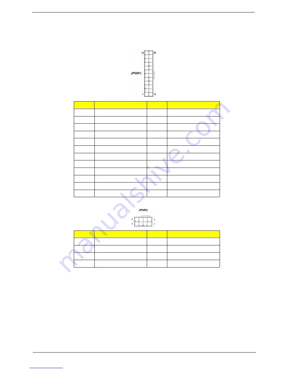
Power Connectors
The ATX 24-pin power connector (JPWR1) allows you to connect an ATX 24-pin or ATX 20-pin power supply.
When using a 20-pin ATX power supply, plug the power supply along with pins 1 and 13. A foolproof design is
on pins 11, 12, 23, and 24 to avoid wrong installation.
The ATX 12V power connector (JPWR2) provides power to the processor.
Important notification about power issue
The NForce chipset is very sensitive to ESD (Electrostatic Discharge), therefore this issue mostly happens
while the users intensively swap memory modules under S5 (power-off) states, and the power cord is plugged
while installing modules. Due to several pins are very sensitive to ESD, so this kind of memory-replacement
actions might cause system chipset unable to boot.
Please follow the following solution to avoid this situation.
1.
Unplug the AC power cable.
2.
Unplug the ATX 24-pin and ATX 12V power connectors before the first installation or during system
upgrade procedure.
Pin
Signal
Pin
Signal
1
+3.3V 13
+3.3V
2
+3.3V
14
-12V
3
GND
15
GND
4
+5V
16
PS-ON#
5
GND
17
GND
6
+5V
18
GND
7
GND
19
GND
8
PWR OK
20
Res
9
5VSB
21
+5V
10
+12V
22
+5V
11
+12V
23
+5V
12
+3.3V
24
GND
Pin
Signal
Pin
Signal
1
GND
5
+12V
2
GND
6
+12V
3
GND
7
+12V
4
GND
8
+12V
Summary of Contents for Aspire Predator G7700 Series
Page 11: ...Chapter 1 3 Dimensions and weight Length 490 mm Height 430 mm Width 190 mm ...
Page 18: ...10 Chapter 1 ...
Page 36: ...28 Chapter 2 ...
Page 47: ...Chapter 3 39 5 Pull the bezel away from the chassis ...
Page 50: ...42 Chapter 3 7 Disconnect the power cables from the video cards then remove the cards ...
Page 57: ...Chapter 3 49 8 Slide the backplane board forward 1 then remove the board from the HDD cage 2 ...
Page 74: ...66 Chapter 3 ...
Page 88: ...80 Chapter 4 ...
Page 89: ...Chapter 5 81 System Block Diagram System Block Diagram and Board Layout Chapter 5 ...
Page 100: ...92 Chapter 6 Aspire G7700 Series Exploded Diagram ...
Page 106: ...98 Chapter 6 ...


