


Chapter 1
9
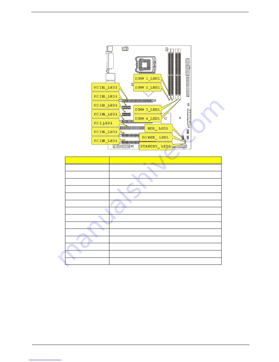
Mainboard LED indicators
The mainboard LED indicators are easy to check the system status when user open the cover or testing the system
board.
LED status
Description
PCIE1 (blue)
Lights when PCI E1 slot is functional.
PCIE2 (blue)
Lights when PCI E2 slot is functional.
PCIE3 (blue)
Lights when PCI E3 slot is functional.
PCIE4 (blue)
Lights when PCI E4 slot is functional.
PCI (blue)
Lights when PCI1 slot is functional.
PCIE5 (blue)
Lights when PCI E5 slot is functional.
PCIE6 (blue)
Lights when PCI E6 slot is functional.
DIMM1 (orange)
Lights when the DIMM1 slot is functional.
DIMM2 (green)
Lights when the DIMM2 slot is functional.
DIMM3 (green)
Lights when the DIMM3 slot is functional.
DIMM4 (orange)
Lights when the DIMM4 slot is functional.
HDD (pink)
Lights when the HDD is functional.
Power (blue)
Lights when the system is powered on.
Standby (pink)
Lights when the system is in standby mode.
Summary of Contents for Aspire Predator G7700 Series
Page 11: ...Chapter 1 3 Dimensions and weight Length 490 mm Height 430 mm Width 190 mm ...
Page 18: ...10 Chapter 1 ...
Page 36: ...28 Chapter 2 ...
Page 47: ...Chapter 3 39 5 Pull the bezel away from the chassis ...
Page 50: ...42 Chapter 3 7 Disconnect the power cables from the video cards then remove the cards ...
Page 57: ...Chapter 3 49 8 Slide the backplane board forward 1 then remove the board from the HDD cage 2 ...
Page 74: ...66 Chapter 3 ...
Page 88: ...80 Chapter 4 ...
Page 89: ...Chapter 5 81 System Block Diagram System Block Diagram and Board Layout Chapter 5 ...
Page 100: ...92 Chapter 6 Aspire G7700 Series Exploded Diagram ...
Page 106: ...98 Chapter 6 ...


