


62
Chapter 3
Removing the Mainboard
1.
See “Removing the Bezel Door” on page 33.
2.
See “Removing the Optical Drive” on page 40.
3.
See “Removing the Video Cards” on page 41.
4.
See “Removing the TV Tuner Card” on page 43.
5.
See “Removing the Card Reader Drive” on page 44.
6.
See “Removing the Backplane Board” on page 48.
7.
See “Removing the Memory Modules” on page 50.
8.
See “Removing the Liquid Cooler Fan Assembly” on page 51.
9.
See “Removing the Processor” on page 54.
10.
See “Removing the Power Supply” on page 56.
11.
See “Removing the HDD Fan” on page 58.
12.
See “Removing the Top Cover” on page 59.
13.
See “Removing the USB Board” on page 60.
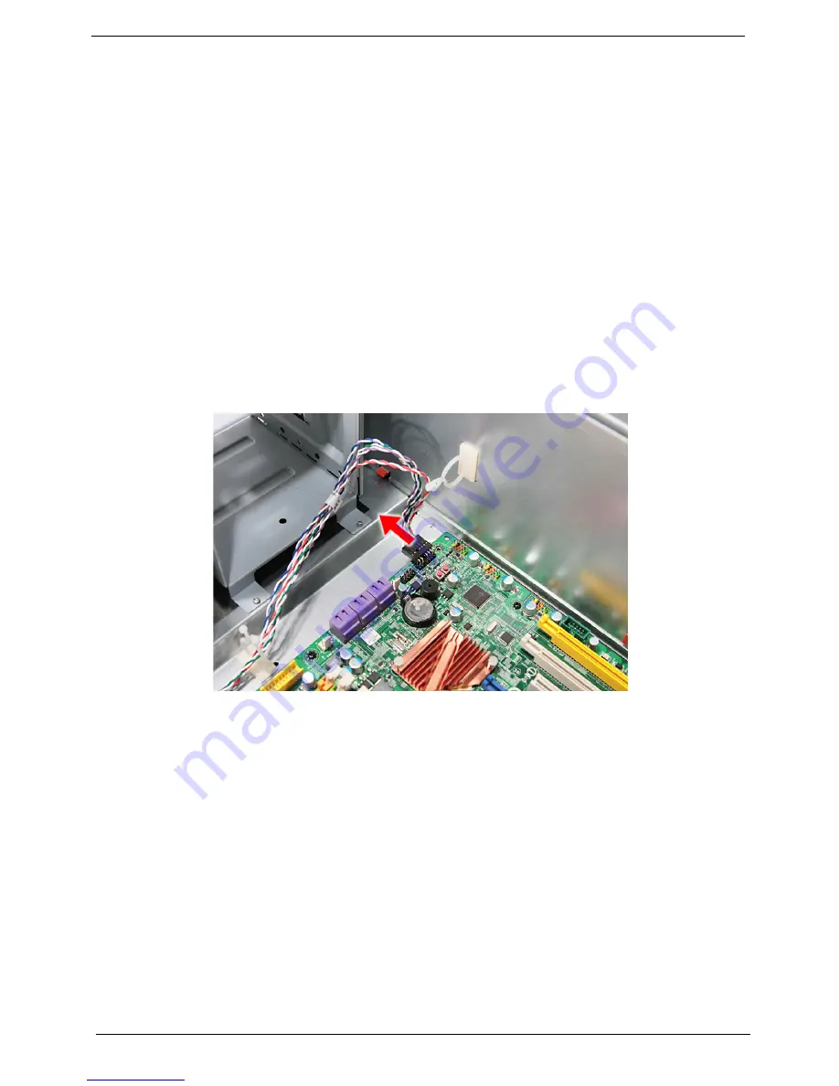
14.
Disconnect the LED cable from the mainboard.
Summary of Contents for Aspire Predator G7700 Series
Page 11: ...Chapter 1 3 Dimensions and weight Length 490 mm Height 430 mm Width 190 mm ...
Page 18: ...10 Chapter 1 ...
Page 36: ...28 Chapter 2 ...
Page 47: ...Chapter 3 39 5 Pull the bezel away from the chassis ...
Page 50: ...42 Chapter 3 7 Disconnect the power cables from the video cards then remove the cards ...
Page 57: ...Chapter 3 49 8 Slide the backplane board forward 1 then remove the board from the HDD cage 2 ...
Page 74: ...66 Chapter 3 ...
Page 88: ...80 Chapter 4 ...
Page 89: ...Chapter 5 81 System Block Diagram System Block Diagram and Board Layout Chapter 5 ...
Page 100: ...92 Chapter 6 Aspire G7700 Series Exploded Diagram ...
Page 106: ...98 Chapter 6 ...


