


34
Chapter 2
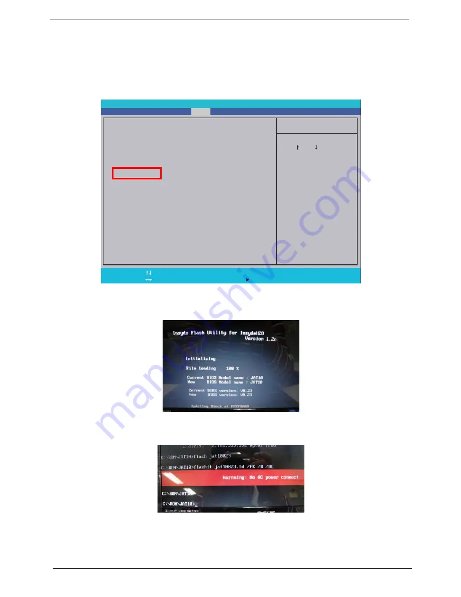
DOS Flash Utility
Perform the following steps to use the DOS Flash Utility:
1.
Press F2 during boot to enter the Setup Menu.
2.
Select Boot Menu to modify the boot priority order, for example, if using USB HDD to Update BIOS, move
USB HDD to position 1.
3.
Execute the FLASH.BAT batch file to update BIOS. Or enter C:\ Flash it bios ver.fd/dc
The flash process begins as shown.
4.
In flash BIOS, the message Please do not remove AC Power Source displays.
NOTE: If the AC power is not connected, the following message displays.
Plug in the AC power to continue.
5.
Flash is complete when the message Flash programming complete displays.
Item S pecificHelp
Use < > or < > to s
elect
a device, then press
<F5> to mo
ve it down the
list, or <F6> to mov
e
it up the li
st. Press
<Esc> to
escape the menu
F 1
E S C
Help
Exit
Select Item
Select Menu
Change V alues
Select
SubMenu
E n t e r
F 9
F 10
Setup Default
Save and Exit
Boot priority order:
1. IDE0 : Hitachi HTS545032B9A300
2. IDE1 :
3. Network Boot : Athero
s Boot Agent
4. USB HDD
5. USB CDROM :
6. USB FDD :
Boot priority order:
1. IDE0 : Hitachi HTS545032B9A300
2. IDE1 :
3. Network Boot : Athero
s Boot Agent
4. USB HDD
5. USB CDROM :
6. USB FDD :
F 5 / F 6
InsydeH20 Setup Utility
Information Main
Boot
Exit
Security
Summary of Contents for ASPIRE ONE 1410
Page 6: ...VI...
Page 10: ...X Table of Contents...
Page 34: ...24 Chapter 1...
Page 50: ...40 Chapter 2...
Page 59: ...Chapter 3 49 9 Detach the HDD board...
Page 61: ...Chapter 3 51 5 Pull the memory module out 6 Repeat steps 4 and 5 for the second memory module...
Page 73: ...Chapter 3 63 7 Unlock the touch pad FCC and pull the cable away...
Page 77: ...Chapter 3 67 4 Lift off the LCD Board 5 Unlock and remove the LED board FCC from the mainboard...
Page 87: ...Chapter 3 77 4 Pull the cables away from the two adhesive locations 5 Lift the modules away...
Page 91: ...Chapter 3 81 5 Roll the bezel up and away from the hinges...
Page 94: ...84 Chapter 3 4 Lift the LCD panel out lifting the bottom of the panel first...
Page 106: ...96 Chapter 3 3 Apply adhesive and stick the microphone down...
Page 117: ...Chapter 3 107 3 Connect the speaker connector...
Page 135: ...Chapter 3 125 4 Tighten the four captive screws...
Page 137: ...Chapter 3 127 4 Place the HDD cover in from one corner 5 Tighten the two captive screws...
Page 140: ...130 Chapter 3...
Page 240: ...230 Appendix A...
Page 250: ...240 Appendix B...
Page 252: ...242...
Page 255: ...245...
Page 256: ...246...


