


Chapter 4
139
8.
Remove and recently installed hardware or software.
9.
Restore system and file settings from a known good date using System Restore.
If the issue is not fixed, repeat the preceding steps and select an earlier time and date.
10. Reinstall the Operating System.
11. If the Issue is still not resolved, see “Online Support Information” on page 241.
Internal Microphone Failure
If the internal Microphone fails, perform the following actions one at a time to correct the problem. Do not
replace non-defective FRUs:
Microphone Problems
If internal or external Microphones do no operate correctly, perform the following actions one at a time to
correct the problem.
1.
Check that the microphone is enabled. Navigate to Start
Control Panel
Hardware and Sound
Sound and select the Recording tab.
2.
Right-click on the Recording tab and select Show Disabled Devices (clear by default).
3.
The microphone appears on the Recording tab.
4.
Right-click on the microphone and select Enable.
5.
Select the microphone then click Properties. Select the Levels tab.
6.
Increase the volume to the maximum setting and click OK.
7.
Test the microphone hardware:
a.
Select the microphone and click Configure.
b.
Select Set up microphone.
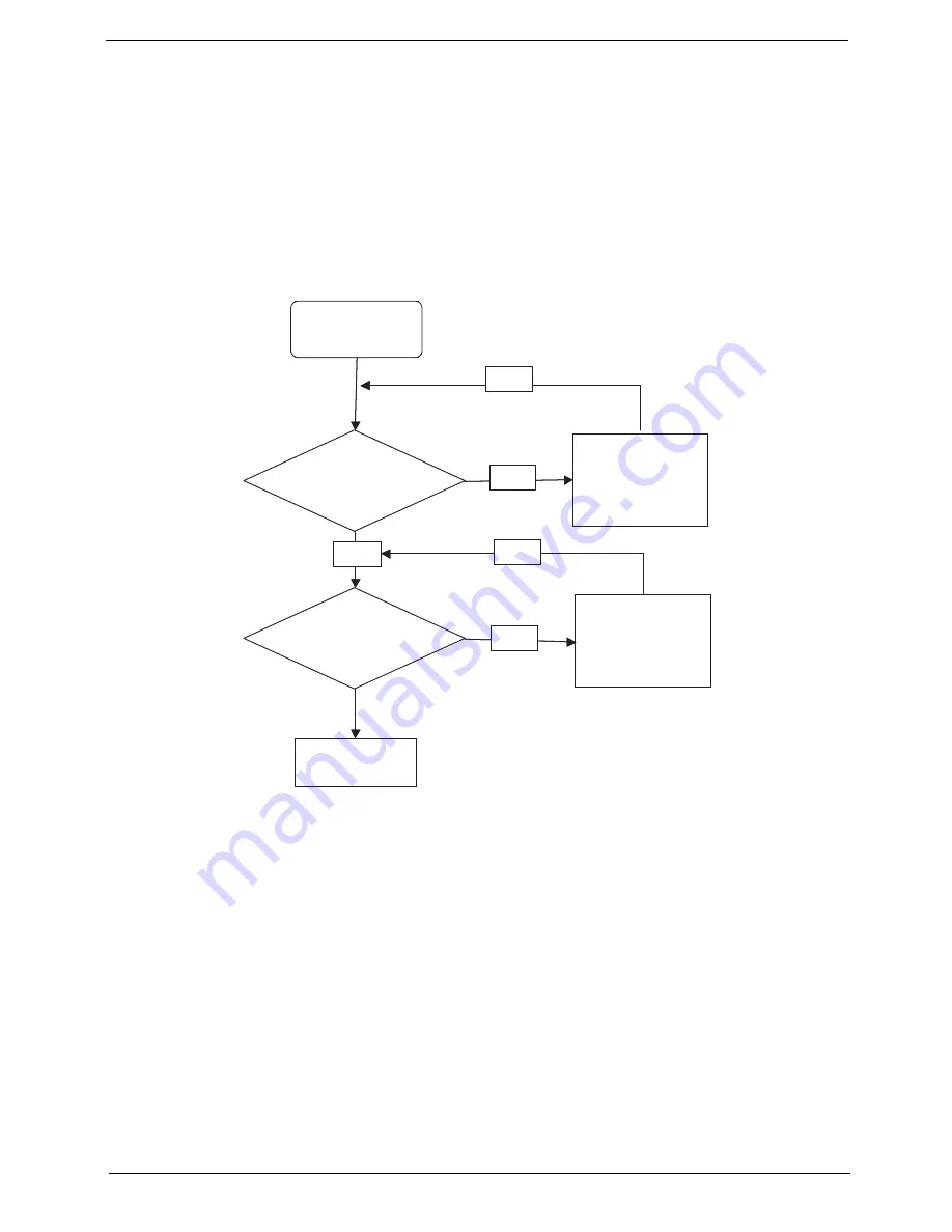
Start
Check M/B Mic.
cable
Re-assemble the
MIC cable to M/B
OK
NG
Check MIC wire
of LCD module
OK
Swap MIC wire of
LCD module
OK
NG
Swap M/B
Start
Check M/B Mic.
cable
Re-assemble the
MIC cable to M/B
OK
NG
Check MIC wire
of LCD module
OK
Swap MIC wire of
LCD module
OK
NG
Swap M/B
Summary of Contents for ASPIRE ONE 1410
Page 6: ...VI...
Page 10: ...X Table of Contents...
Page 34: ...24 Chapter 1...
Page 50: ...40 Chapter 2...
Page 59: ...Chapter 3 49 9 Detach the HDD board...
Page 61: ...Chapter 3 51 5 Pull the memory module out 6 Repeat steps 4 and 5 for the second memory module...
Page 73: ...Chapter 3 63 7 Unlock the touch pad FCC and pull the cable away...
Page 77: ...Chapter 3 67 4 Lift off the LCD Board 5 Unlock and remove the LED board FCC from the mainboard...
Page 87: ...Chapter 3 77 4 Pull the cables away from the two adhesive locations 5 Lift the modules away...
Page 91: ...Chapter 3 81 5 Roll the bezel up and away from the hinges...
Page 94: ...84 Chapter 3 4 Lift the LCD panel out lifting the bottom of the panel first...
Page 106: ...96 Chapter 3 3 Apply adhesive and stick the microphone down...
Page 117: ...Chapter 3 107 3 Connect the speaker connector...
Page 135: ...Chapter 3 125 4 Tighten the four captive screws...
Page 137: ...Chapter 3 127 4 Place the HDD cover in from one corner 5 Tighten the two captive screws...
Page 140: ...130 Chapter 3...
Page 240: ...230 Appendix A...
Page 250: ...240 Appendix B...
Page 252: ...242...
Page 255: ...245...
Page 256: ...246...


