126
Chapter 3
Replacing the Hard Disk Drive
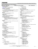
DISCLAIMER: The notebook sample in the following images shows an FFC. The actual model
includes an FPC as pictured in the image on the right.
1.
Connect the HDD FPC to the HDD.
2.
Lift up the clear plastic tab and place the HDD into its bay.
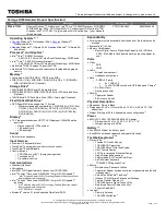
3.
Connect the HDD FPC to the main board.
NOTE: The cable pictured in the above images may differ from the actual sample.
Summary of Contents for ASPIRE ONE 1410
Page 6: ...VI...
Page 10: ...X Table of Contents...
Page 34: ...24 Chapter 1...
Page 50: ...40 Chapter 2...
Page 59: ...Chapter 3 49 9 Detach the HDD board...
Page 61: ...Chapter 3 51 5 Pull the memory module out 6 Repeat steps 4 and 5 for the second memory module...
Page 73: ...Chapter 3 63 7 Unlock the touch pad FCC and pull the cable away...
Page 77: ...Chapter 3 67 4 Lift off the LCD Board 5 Unlock and remove the LED board FCC from the mainboard...
Page 87: ...Chapter 3 77 4 Pull the cables away from the two adhesive locations 5 Lift the modules away...
Page 91: ...Chapter 3 81 5 Roll the bezel up and away from the hinges...
Page 94: ...84 Chapter 3 4 Lift the LCD panel out lifting the bottom of the panel first...
Page 106: ...96 Chapter 3 3 Apply adhesive and stick the microphone down...
Page 117: ...Chapter 3 107 3 Connect the speaker connector...
Page 135: ...Chapter 3 125 4 Tighten the four captive screws...
Page 137: ...Chapter 3 127 4 Place the HDD cover in from one corner 5 Tighten the two captive screws...
Page 140: ...130 Chapter 3...
Page 240: ...230 Appendix A...
Page 250: ...240 Appendix B...
Page 252: ...242...
Page 255: ...245...
Page 256: ...246...