Chapter 1
5
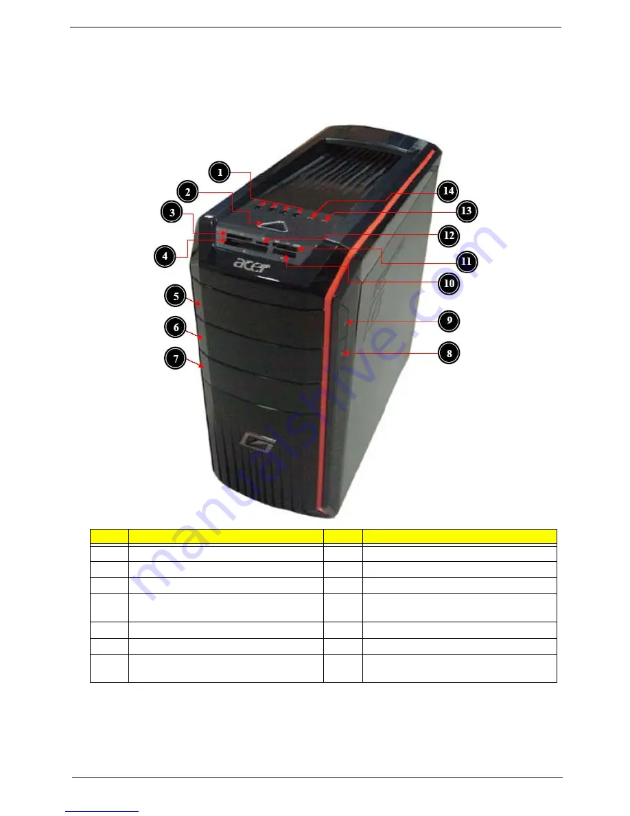
System Components
This section is a virtual tour of the system’s interior and exterior components.
Front Panel
No.
Component
1
USB 2.0 ports
8
Slave optical drive button
2
Power button
9
Master optical drive button
3
XD(XD-Picture) slot
10
MS/MS PRO slot
4
CF I/II (CompactFlash Type I/II) slot
11
SD/MMC(Secure Digital/MultiMedia
Card)slot
5
Master optical drive
12
Micro SD slot
6
Slave optical drive
13
Microphone-in jack
7
Removable HDD bay(Removable HDD bay
for XXX bezel)
14
Headphone/Speaker-out/line-out jack
Summary of Contents for Aspire G3610
Page 1: ...Acer Predator G3610 Service Guide PRINTED IN TAIWAN ...
Page 12: ...4 Chapter 1 Block Diagram ...
Page 48: ...40 Chapter 3 d Remove the three screws e Pull the bracket of removable HDD from the chassis ...
Page 74: ...66 Chapter 3 Install the I O Shielding 1 Install I O shielding into chassis ...
Page 76: ...68 Chapter 3 5 Connect the ATX 24Pin Power cable and ATX 4Pin Power cable to main board ...
Page 91: ...Chapter 3 83 3 Close the PCI Latch then fix the four screws ...
Page 101: ...93 Chapter 4 b Select Proceed with flash update and Press Enter ...
Page 103: ...Chapter 5 95 M B Placement Jumper and Connector Information Chapter 5 ...


