Chapter 1
9
NOTE:
The 2-in1 card reader will be on the front left for UMA models and on the front right for discrete models.
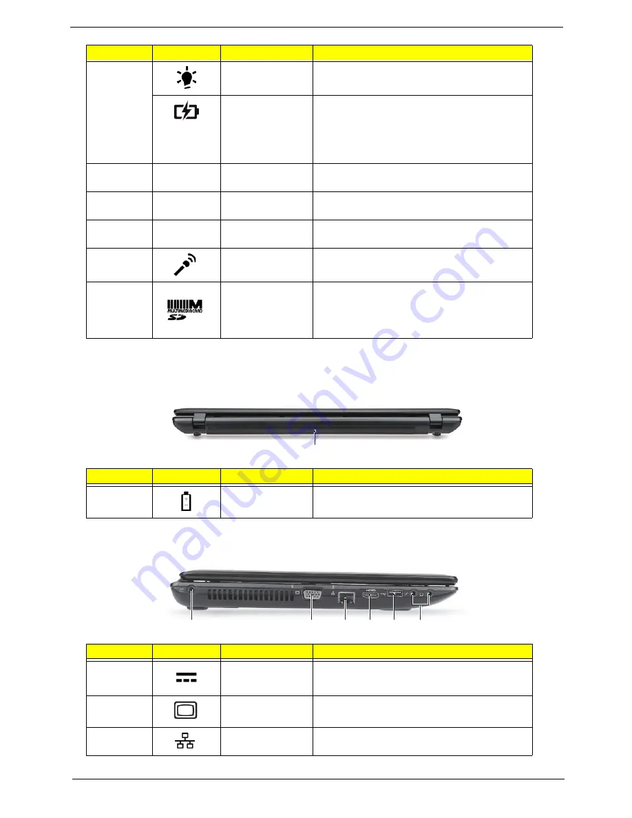
Rear View
Left View
7
Power
Indicates the computer’s power status.
Battery
Indicates the computer’s battery status.
1.
Charging: The light shows amber when the
battery is charging.
2.
Fully charged: The light shows blue when in
AC mode.
8
Click buttons (left
and right)
The left and right buttons function like the left
and right mouse buttons.
9
Palmrest
Comfortable support area for your hands when
you use the computer.
10
Speakers
Left and right speakers deliver stereo audio
output.
11
Microphone
Internal microphone for recording sound.
2-in-1 card
reader
Accepts Secure Digital (SD), MultiMediaCard
(MMC).
Note: Push to remove/install the card. Only
one card can operate at any given time.
No.
Icon
Item
Description
1
Battery bay
Houses the computer's battery pack.
No.
Icon
Item
Description
1
DC-in jack
Connects to an AC adapter
2
External display
(VGA) port
Connects to a display device
(e.g. external monitor, LCD projector).
3
Ethernet (RJ-45)
port
Connects to an Ethernet 10/100/1000-based
network.
No.
Icon
Item
Description
1
2
6
5
4
3
1
Summary of Contents for ASPIRE 5252
Page 4: ...IV ...
Page 10: ...X Table of Contents ...
Page 38: ...28 Chapter 1 ...
Page 69: ...Chapter 3 59 4 Detach the WLAN module from the WLAN socket ...
Page 86: ...76 Chapter 3 5 Lift the Bluetooth cable from the cable guides Discrete UMA ...
Page 97: ...Chapter 3 87 8 Remove the LCD assembly from the lower cover ...
Page 108: ...98 Chapter 3 5 Lift the microphone set clear of the panel ...
Page 119: ...Chapter 3 109 4 Replace the adhesive tape securing the inverter board cable to the LCD cover ...
Page 125: ...Chapter 3 115 7 Replace the adhesive tape to secure the antennas to the lower cover ...
Page 136: ...126 Chapter 3 4 Connect the USB cable to the mainboard and lock the connector ...
Page 144: ...134 Chapter 3 4 Connect the speaker cable B 5 Connect and lock the touchpad FFC C ...
Page 148: ...138 Chapter 3 4 Slide the HDD module in the direction of the arrow to connect the interface ...
Page 158: ...148 Chapter 3 ...
Page 186: ...176 Chapter 3 ...
Page 254: ...244 Appendix B ...
Page 256: ...246 Appendix C ...
Page 260: ...250 ...


