Chapter 1
27
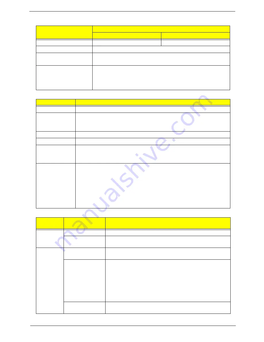
Card Reader
System LED Indicator
Power Specification
Item
Specification
Discrete
UMA
Chipset
RTS5160
RealTek RTS5137
Package
2-in-1 card reader
Feature
USB 2.0 Interface
Push-push type
Supports Maximum size
(please specify max
supporting size for each
card)
SD: 2GB
SDHC: 4GB~32GB
SDXC:64GB~2TB
MMC: Max 128 GB in LBA mode (28-bit sector address)
Item
Specification
Lock
Display on panel (Launch Manager)
System state
Blue color solid on: System on
Blue color off: System off
Amber color blinking: S3 state
HDD access state
Blue color led blinking
Wireless state
Amber color if a wireless device is active
Power button
backlight
Blue color solid on: System on
Blue color off: System off
Amber color blinking: S3 state
Battery state
Charging
•
Amber solid on - Battery charging with AC
•
Blue color solid on - Battery full
•
Amber blinking - Battery abnormal stop charge or batter in low power state
Discharging
•
Amber and blinking - Battery in critical low state
•
Blue / Amber color off - Discharging state
Legacy
Mode
ACPI Mode
Power Management
Off
Mech. Off (G3)
All devices in the system are turned off completely.
Soft Off (G2/S5)
OS initiated shutdown. All devices in the system are turned off
completely.
On
Working (G0/S0)
Individual devices such as the CPU and hard disk may be power
managed in this state.
S3 Sleeping State
CPU set power down
VGA suspend
PCMCIA suspend
Audio power down
Hard Disk power down
CD-ROM power down
Super I/O low power mode
S4 Sleeping State
Also called Hibernate state. The system saves all system states
and data onto disk prior to powering off the whole system.
Summary of Contents for ASPIRE 5252
Page 4: ...IV ...
Page 10: ...X Table of Contents ...
Page 38: ...28 Chapter 1 ...
Page 69: ...Chapter 3 59 4 Detach the WLAN module from the WLAN socket ...
Page 86: ...76 Chapter 3 5 Lift the Bluetooth cable from the cable guides Discrete UMA ...
Page 97: ...Chapter 3 87 8 Remove the LCD assembly from the lower cover ...
Page 108: ...98 Chapter 3 5 Lift the microphone set clear of the panel ...
Page 119: ...Chapter 3 109 4 Replace the adhesive tape securing the inverter board cable to the LCD cover ...
Page 125: ...Chapter 3 115 7 Replace the adhesive tape to secure the antennas to the lower cover ...
Page 136: ...126 Chapter 3 4 Connect the USB cable to the mainboard and lock the connector ...
Page 144: ...134 Chapter 3 4 Connect the speaker cable B 5 Connect and lock the touchpad FFC C ...
Page 148: ...138 Chapter 3 4 Slide the HDD module in the direction of the arrow to connect the interface ...
Page 158: ...148 Chapter 3 ...
Page 186: ...176 Chapter 3 ...
Page 254: ...244 Appendix B ...
Page 256: ...246 Appendix C ...
Page 260: ...250 ...


