


System Utilities
2-1
System Utilities
BIOS Setup Utility
0
A hardware configuration program built into a computer’s BIOS (Basic Input/Output System).
Preconfigured and optimized so users do not need to run this utility. If configuration problems
occur, users may need to run Setup. Refer to Chapter 4, Troubleshooting when problem
arises.
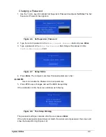
To activate the BIOS Utility, press
F2
during POST when prompted at the bottom of screen.
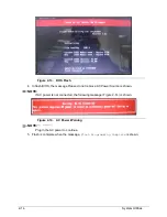
The default parameter of F12 Boot Menu is set to disabled. To change boot device without
entering BIOS Setup Utility, set the parameter to enabled.
To change boot device without entering the BIOS SETUP, Press <
F12
> during POST to enter
multi-boot menu.
Navigating the BIOS Utility
0
Five menu options are:
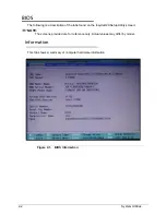
Information
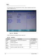
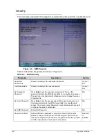
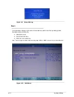
Main
Security
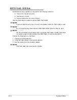
Boot
Exit
To navigate through the following:
Menu - use the left and right arrow keys
Item - use the up and down arrow keys
Change parameter value - press
F5
or
F6
.
Exit - Press
Esc
Load default settings - press
F9
. Press
F10
to save changes and exit BIOS Setup Utility
NOTE:
NOTE
:
Parameter values can be changed if enclosed in square brackets [ ]. Navigation keys
appear at the bottom of the screen. Read parameter help carefully when making
changes to parameter values. Parameter help is found in the Item Specific Help area of
the screen. System information is subject to specific models.
Summary of Contents for Aspire 3750
Page 1: ...Acer AS3750 AS3750G SERVICEGUIDE ...
Page 4: ...iv ...
Page 40: ...1 36 Hardware Specifications and Configurations ...
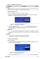
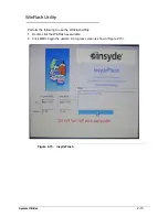
Page 57: ...System Utilities 2 17 Figure 2 19 Unlock Password ...
Page 75: ...3 15 Figure 3 24 Memory Module Figure 3 25 Memory Module ...
Page 79: ...3 19 ...
Page 83: ...3 23 Top case disassembly M2 5 3 5L 3 Table 3 1 Step Screw Quantity Screw Type ...
Page 87: ...3 27 2 Disconnect the RTC BATTERY cable then take the battery away Figure 3 45 RTC BATTERY ...
Page 94: ...3 34 Figure 3 58 LCD Module ...
Page 98: ...3 38 Figure 3 65 LCD Panel ...
Page 101: ...3 41 Figure 3 70 Hinge ...
Page 103: ...3 43 Figure 3 73 CPU Module Figure 3 74 CPU Module ...
Page 105: ...3 45 Figure 3 77 Main board Figure 3 78 Main board ...
Page 108: ...3 48 Figure 3 83 Blue tooth Module Figure 3 84 Blue tooth Module ...
Page 112: ...3 52 Figure 3 91 Top case Figure 3 92 Top case ...
Page 115: ...3 55 Figure 3 97 Memory Figure 3 98 Memory ...
Page 163: ...FRU Field Replaceable Unit List 6 9 ...
Page 192: ...6 38 FRU Field Replaceable Unit List ...
Page 268: ...7 76 Model Definition and Configuration ...
Page 272: ...8 4 Test Compatible Components ...


