


Hardware Specifications and Configurations
1-7
7
Click buttons (left, and
right)
The left and right buttons function like the left
and right mouse buttons.
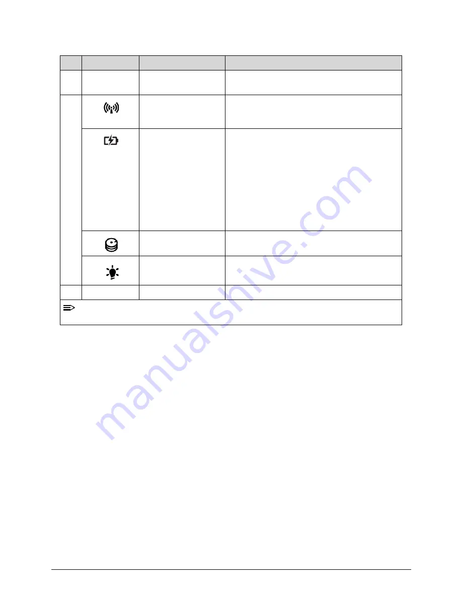
8
Communication
Indicator
Enables/disables the computer’s
communication devices. (Communication
devices may vary by configuration.)
Battery Indicator
Charging
Amber solid on - Battery charging with AC
Blue color solid on - Battery full
Amber blinking - Battery abnormal stop charge
or batter in low power state
Discharging
Amber and blinking - Battery in critical low state
Amber color off - Discharging state.
Hard Disk Drive
(HDD) indicator
Indicates when the hard disk drive is active.
Power indicator
Indicates the computer’s power status.
9
Speakers
Deliver stereo audio output.
NOTE:
The front panel indicators are visible even when the computer cover is closed up.
Table 1-1. Top View (Continued)
No
Icon
Item
Description
Summary of Contents for Aspire 3750
Page 1: ...Acer AS3750 AS3750G SERVICEGUIDE ...
Page 4: ...iv ...
Page 40: ...1 36 Hardware Specifications and Configurations ...
Page 57: ...System Utilities 2 17 Figure 2 19 Unlock Password ...
Page 75: ...3 15 Figure 3 24 Memory Module Figure 3 25 Memory Module ...
Page 79: ...3 19 ...
Page 83: ...3 23 Top case disassembly M2 5 3 5L 3 Table 3 1 Step Screw Quantity Screw Type ...
Page 87: ...3 27 2 Disconnect the RTC BATTERY cable then take the battery away Figure 3 45 RTC BATTERY ...
Page 94: ...3 34 Figure 3 58 LCD Module ...
Page 98: ...3 38 Figure 3 65 LCD Panel ...
Page 101: ...3 41 Figure 3 70 Hinge ...
Page 103: ...3 43 Figure 3 73 CPU Module Figure 3 74 CPU Module ...
Page 105: ...3 45 Figure 3 77 Main board Figure 3 78 Main board ...
Page 108: ...3 48 Figure 3 83 Blue tooth Module Figure 3 84 Blue tooth Module ...
Page 112: ...3 52 Figure 3 91 Top case Figure 3 92 Top case ...
Page 115: ...3 55 Figure 3 97 Memory Figure 3 98 Memory ...
Page 163: ...FRU Field Replaceable Unit List 6 9 ...
Page 192: ...6 38 FRU Field Replaceable Unit List ...
Page 268: ...7 76 Model Definition and Configuration ...
Page 272: ...8 4 Test Compatible Components ...


