


Hardware Specifications and Configurations
1-33
HDMI Port
AC Adapter
System Power Management
Card Reader
Item
Specification
Compliance level
HDMI1.4a
Data thoroughput
Up to 16.7 million colors
Number of HDMI port(s)
1
Location
JHDMI1 at the left side
Item
Specification
Input rating
65W(Internal VGA)/90W(OPTIMUS)
Maximum input AC current
3.42A/4.74A
Inrush current
I
2
t at 264V
Efficiency
84% Min at normal input voltage
Item
Specification
Mech. Off (G3)
All devices in the system are turned off completely.
Soft Off (G2/S5)
OS initiated shutdown. All devices in the system are turned off
completely.
Working (G0/S0)
Individual devices like CPU and hard disc can be power
managed.
Suspend to RAM (S3)
CPU set power down, VGA Suspend, PCMCIA SuspendAudio,
Power Down, Hard Disk Power Down, CD-ROM Power Down,
Super I/O Low Power mode.
Save to Disk (S4)
Also called Hibernation Mode. System saves all system states
and data onto the disc prior to power off the whole system.
Item
Specification
Chipset
Realtek RTS5209-GR
Package
LQFN 48P
Maximum supported size
SD: 2T, MMC: 16G, miniSD: 16G, MS:32G, xD:8G
Features
Supports SD Extended Capacity (SDXC), compliant with the
SD Memory Card Specification Version 3.0.
Summary of Contents for Aspire 3750
Page 1: ...Acer AS3750 AS3750G SERVICEGUIDE ...
Page 4: ...iv ...
Page 40: ...1 36 Hardware Specifications and Configurations ...
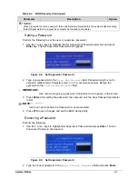
Page 57: ...System Utilities 2 17 Figure 2 19 Unlock Password ...
Page 75: ...3 15 Figure 3 24 Memory Module Figure 3 25 Memory Module ...
Page 79: ...3 19 ...
Page 83: ...3 23 Top case disassembly M2 5 3 5L 3 Table 3 1 Step Screw Quantity Screw Type ...
Page 87: ...3 27 2 Disconnect the RTC BATTERY cable then take the battery away Figure 3 45 RTC BATTERY ...
Page 94: ...3 34 Figure 3 58 LCD Module ...
Page 98: ...3 38 Figure 3 65 LCD Panel ...
Page 101: ...3 41 Figure 3 70 Hinge ...
Page 103: ...3 43 Figure 3 73 CPU Module Figure 3 74 CPU Module ...
Page 105: ...3 45 Figure 3 77 Main board Figure 3 78 Main board ...
Page 108: ...3 48 Figure 3 83 Blue tooth Module Figure 3 84 Blue tooth Module ...
Page 112: ...3 52 Figure 3 91 Top case Figure 3 92 Top case ...
Page 115: ...3 55 Figure 3 97 Memory Figure 3 98 Memory ...
Page 163: ...FRU Field Replaceable Unit List 6 9 ...
Page 192: ...6 38 FRU Field Replaceable Unit List ...
Page 268: ...7 76 Model Definition and Configuration ...
Page 272: ...8 4 Test Compatible Components ...


