


Hardware Specifications and Configurations
1-35
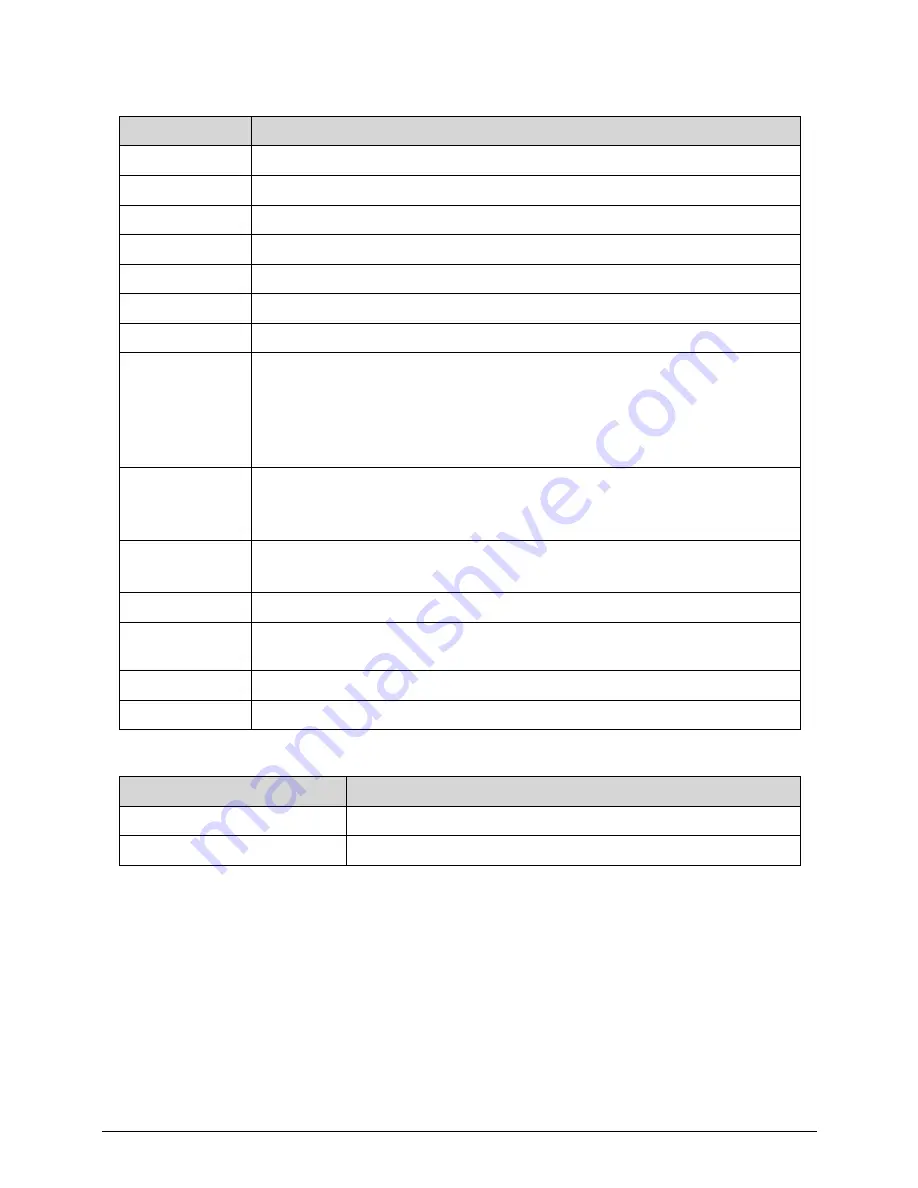
System Interrupt Specification
System IO Address Map
Hardware IRQ
System function
IRQ00
System timer
IRQ01
Standard PS/2 Keyboard
IRQ08
System CMOS/real time clock
IRQ12
Synaptics PS/2 Port TouchPad
IRQ13
Numeric data processor
IRQ81 - IRQ190
Microsoft ACPI-Compliant System
IRQ10
Intel(R) 6 Series/C200 Series Chipset Family SMBUS Controller - 1C22
IRQ16
Intel(R) 6 Series/C200 Series Chipset Family USB Enhanced Host Controller
- 1C2D
Intel(R) 6 Series/C200 Series Chipset Family PCI Express Rott Port2 - 1C12
Intel(R) 6 Series/C200 Series Chipset Family PCI Express Rott Port6 - 1C1A
Intel(R) 6 Management Engine Interface
IRQ17
Atheros AR5B97 Wireless Network Adapter
Atheros AR8151 PCI-E Gigabit Ethernet Controller (NIS 6.20)
Intel(R) 6 Series/C200 Series Chipset Family PCI Express Rott Port1 - 1C10
IRQ19
Intel(R) 6 Series/C200 Series Chipset Family PCI Express Rott Port4 - 1C16
Intel(R) Mobile Express Chipset SATA AHCI Controller
IRQ22
High Definition Audio Controller
IRQ23
Intel(R) 6 Series/C200 Series Chipset Family USB Enhanced Host Controller
- 1C26
IRQ-3 - IRQ-10
Renesas Electronic USB 3.0 Host Controller
IRQ-2
Intel(R) HD Graphics Family
I/O address (hex)
System Function (shipping configuration)
000 - CF7
PCI bus
0D00 - FFFF
PCI bus
Summary of Contents for Aspire 3750
Page 1: ...Acer AS3750 AS3750G SERVICEGUIDE ...
Page 4: ...iv ...
Page 40: ...1 36 Hardware Specifications and Configurations ...
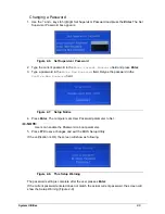
Page 57: ...System Utilities 2 17 Figure 2 19 Unlock Password ...
Page 75: ...3 15 Figure 3 24 Memory Module Figure 3 25 Memory Module ...
Page 79: ...3 19 ...
Page 83: ...3 23 Top case disassembly M2 5 3 5L 3 Table 3 1 Step Screw Quantity Screw Type ...
Page 87: ...3 27 2 Disconnect the RTC BATTERY cable then take the battery away Figure 3 45 RTC BATTERY ...
Page 94: ...3 34 Figure 3 58 LCD Module ...
Page 98: ...3 38 Figure 3 65 LCD Panel ...
Page 101: ...3 41 Figure 3 70 Hinge ...
Page 103: ...3 43 Figure 3 73 CPU Module Figure 3 74 CPU Module ...
Page 105: ...3 45 Figure 3 77 Main board Figure 3 78 Main board ...
Page 108: ...3 48 Figure 3 83 Blue tooth Module Figure 3 84 Blue tooth Module ...
Page 112: ...3 52 Figure 3 91 Top case Figure 3 92 Top case ...
Page 115: ...3 55 Figure 3 97 Memory Figure 3 98 Memory ...
Page 163: ...FRU Field Replaceable Unit List 6 9 ...
Page 192: ...6 38 FRU Field Replaceable Unit List ...
Page 268: ...7 76 Model Definition and Configuration ...
Page 272: ...8 4 Test Compatible Components ...


