40
Chapter 3
4.
Remove the battery pack.
Disassembly Process
The disassembly process is divided into the following sections:
•
External components disassembly
•
Main unit disassembly
•
LCD module disassembly
The flowcharts provided in the succeeding disassembly sections illustrate the entire disassembly sequence.
Observe the order of the sequence to avoid damage to any of the hardware components. For example, if you
want to remove the Mainboard, you must first remove the Keyboard, and LCD Module then disassemble the
inside assembly frame in that order.
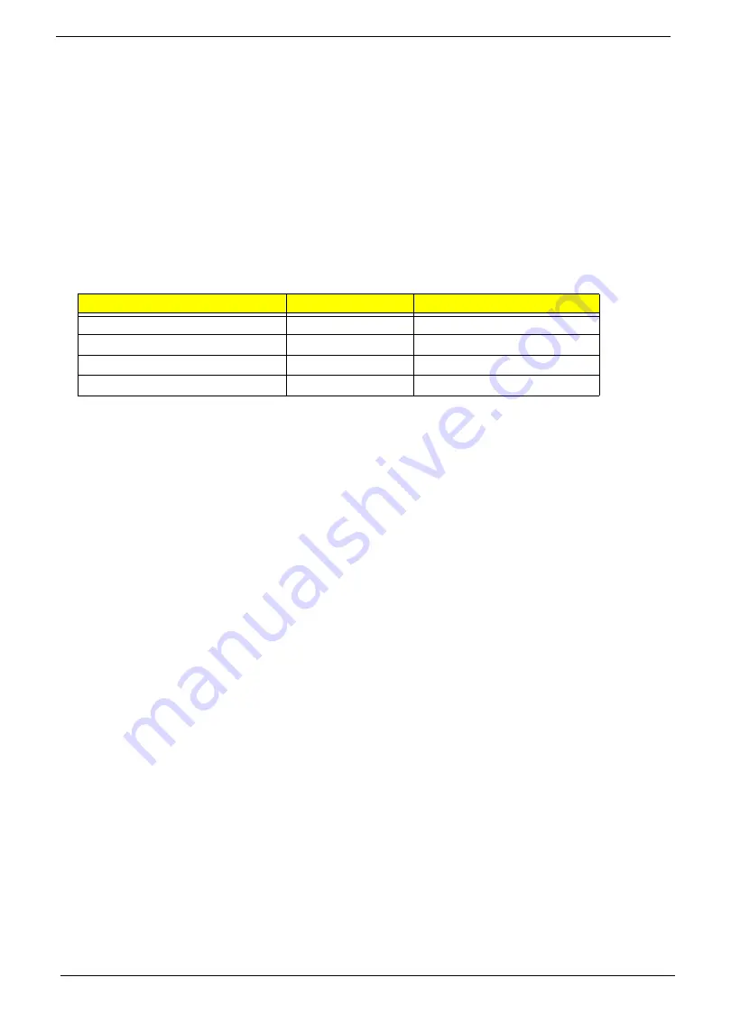
Main Screw List
Screw
Quantity
Part Number
M2*2.5 (silver)
8
86.TPK07.001
M2*3
7
86.ARE07.002
M2*4
26
86.W0107.003
M2*5
24
86.TG607.004
Summary of Contents for Aspire 1420P Series
Page 6: ...vi...
Page 10: ...x Table of Contents...
Page 13: ...Chapter 1 3 System Block Diagram...
Page 32: ...22 Chapter 1...
Page 48: ...38 Chapter 2...
Page 64: ...54 Chapter 3 4 Unlock the FPC 5 Remove the FPC and keyboard...
Page 66: ...56 Chapter 3 4 Remove the hinge cap 5 Remove the hinge bezel...
Page 70: ...60 Chapter 3 10 Pull the upper cover away...
Page 94: ...84 Chapter 3 7 Pry up the bezel top edge and remove...
Page 119: ...Chapter 3 109 7 Insert the stylus...
Page 148: ...138 Chapter 3 2 Replace the HDD in the bay 3 Adhere the black tape 4 Replace the HDD FPC...
Page 202: ...192 Appendix A...
Page 212: ...202...
Page 215: ...205...
Page 216: ...206...

