


Chapter 1
15
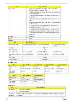
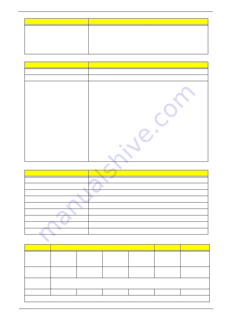
South Bridge Specifications
System Memory
Hard Disk Drive Interface
Features
•
Processor host bus supports 667/800/1066Mhz FSB support.
•
Supports Dual Channel DDR3 SD-RAM at 800/1066MHz.
•
Integrated SDRAM controller up to *GB (2 SODIMM support)
•
DMI x2 and DMI x4 for connection between GMCH and
ICH9M.
Item
Specification
Chipset
ICH9M SFF
Package
BGA 676 balls
Features
•
Upstream accelerated Hub architecture interface for access to
GMCH.
•
PCI Express Base Specification, Revision 1.1 support.
•
PCI 2.3 interface. (4 PCI Request/Grant pairs).
•
ACPI Power Management Logic Support. Enhanced DMA
controller, interrupt controller, timers functions.
•
Integrated Serial ATA host controllers with independent DMA
operation on six ports and AHCI support.
•
USB 1.1 & USB 2.0 Host controllers.
•
Supports Intel High Definition Audio (Intel HD Audio) Interface.
•
Supports Intel® Matrix Storage Technology.
•
Supports Intel® Active Management Technology.
•
Low Pin Count (LPC) interface.
•
6 PCIe ports.
Item
Specification
Memory size
0MB (No on-board Memory)
DIMM socket number
2 sockets
Supports memory size per socket
2GB
Supports maximum memory size
4GB for 64bit OS (with two 2GB SO-DIMM)
Supports DIMM type
DDR3 Synchronous DRAM
Supports DIMM Speed
800 MHz
Supports DIMM voltage
1.5V
Supports DIMM package
204-pin DDR3-800 SO-DIMM
Module Combination
Any combination permissible within the above specifications.
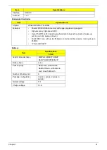
Item
Specifications
Vendor &
Model
Name
Hitachi
HTS545050B
9A300
Hitachi
HTS545032B
9A300
Hitachi
HTS545025B
9A300
Hitachi
HTS545016B
9A300
Hitachi
HTS543225L
9A300
Hitachi
HTS543216L9
SA00
Capacity
(GB)
500
320
250
160
250
160
Bytes per
sector
512
Data heads
4
3
2
2
3
2
Drive Format
Item
Specification
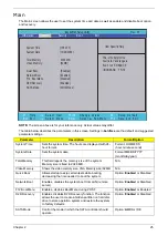
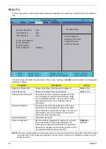
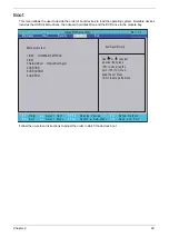
Summary of Contents for Aspire 1420P Series
Page 6: ...vi...
Page 10: ...x Table of Contents...
Page 13: ...Chapter 1 3 System Block Diagram...
Page 32: ...22 Chapter 1...
Page 48: ...38 Chapter 2...
Page 64: ...54 Chapter 3 4 Unlock the FPC 5 Remove the FPC and keyboard...
Page 66: ...56 Chapter 3 4 Remove the hinge cap 5 Remove the hinge bezel...
Page 70: ...60 Chapter 3 10 Pull the upper cover away...
Page 94: ...84 Chapter 3 7 Pry up the bezel top edge and remove...
Page 119: ...Chapter 3 109 7 Insert the stylus...
Page 148: ...138 Chapter 3 2 Replace the HDD in the bay 3 Adhere the black tape 4 Replace the HDD FPC...
Page 202: ...192 Appendix A...
Page 212: ...202...
Page 215: ...205...
Page 216: ...206...


