


3
External and internal structure
Front panel
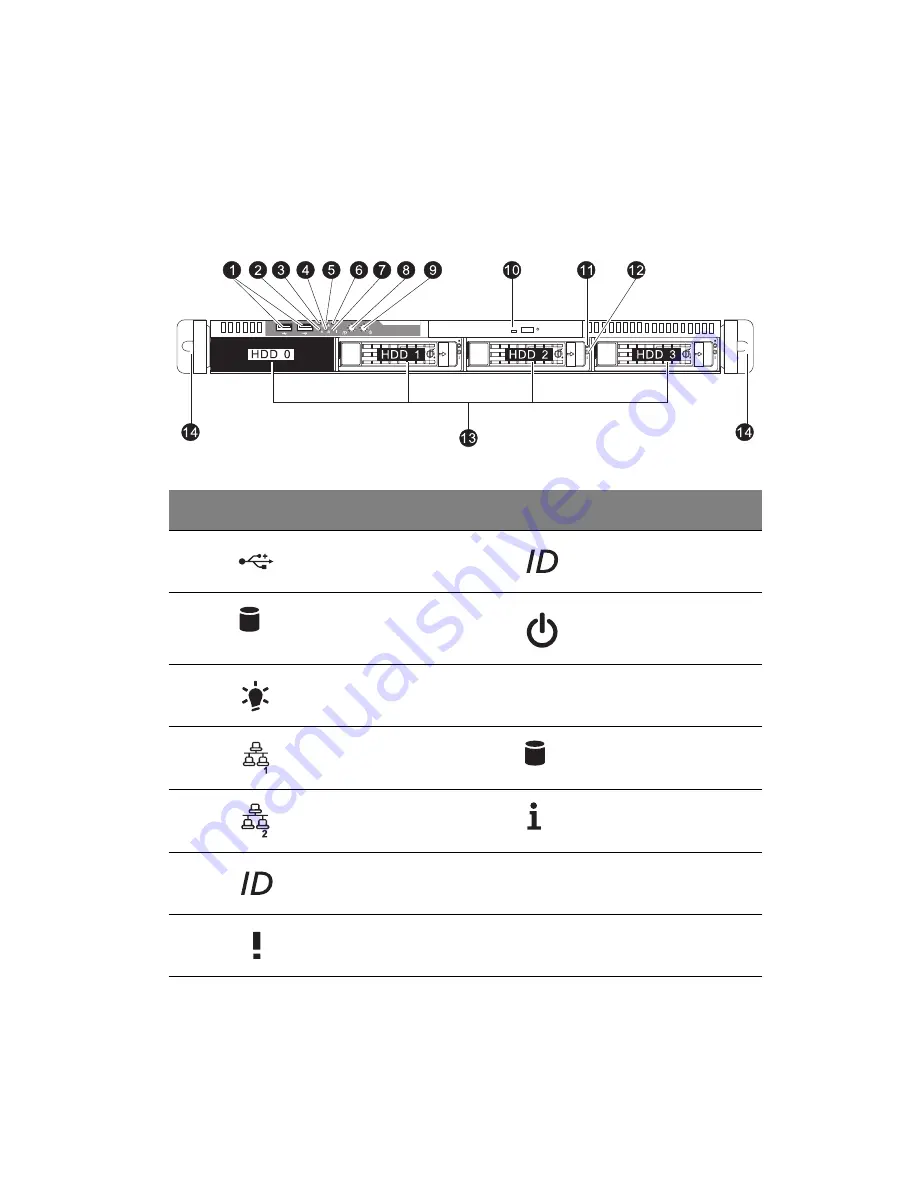
The illustration below shows the system front panel.
No.
Icon
Component
No.
Icon
Component
1
USB 2.0 ports
8
System ID button
2
HDD activity
indicator
9
Power button
3
Power indicator
10
Optical drive bay
4
LAN1 activity
indicator
11
Hot-plug HDD activity
indicator
5
LAN2 activity
indicator
12
Hot-plug HDD status
indicator
6
System ID indicator
13
3.5-inch hard disk
drive (HDD) bays
7
Status/fault
indicator
14
Rack handles
Summary of Contents for AR320 F1 Series
Page 1: ...AR320 F1 Series User Guide ...
Page 14: ...xiv ...
Page 18: ...xviii ...
Page 19: ...1 System tour ...
Page 31: ...2 System setup ...
Page 38: ...2 System setup 20 ...
Page 39: ...3 System upgrades ...
Page 71: ...4 System BIOS ...
Page 104: ...4 System BIOS 86 ...
Page 105: ...5 System troubleshooting ...
Page 116: ...5 System troubleshooting 98 ...
Page 117: ...Appendix A Server management tools ...
Page 123: ...Appendix B Rack mount configuration ...
Page 132: ...Appendix C Acer Smart Console ...
Page 171: ...153 ...


